Assembly for an aircraft, the assembly including a pylon and a tank containing an extinguisher fluid

Active Publication Date: 2021-06-24
AIRBUS OPERATIONS SAS
0 Cites 0 Cited by

AI-Extracted Technical Summary

Problems solved by technology

This procedure is relatively lengthy and complicate...

Method used

[0044]To facilitate placing the tank 102 in the operating position in the pylon 12, the assembly 50 includes rails 116 that are fixed inside the pylon 12 and extend parallel to the direction of introduction. The rails 116 are disposed in line with the lower edge of the window 18. The rails 116 are, for example, fixed to the box section of the pylon 12.
[0053...

Benefits of technology

[0016]This kind of assembly enables simple and rapid ...

Abstract

An assembly for an aircraft, the assembly including a pylon with a lateral wall pierced by a window, a tank with a neck blocked by a film and carrying a first anchoring arrangement, and a fixing arrangement for fixing at least a part of the tank bearing the neck inside the pylon, a discharge pipe, and a discharge head. The head includes an explosive cartridge and a hole with a second anchoring arrangement in which discharges the discharge pipe. The discharge head is fixed inside the pylon facing the window. The explosive cartridge is designed to generate in the hole a shockwave sufficient to rupture the film An assembly of this kind enables simple and rapid removal of the tank from and installation thereof inside the pylon.

Application Domain

Power plant fuel tanksAircraft power plant components +5

Technology Topic

AirplaneStructural engineering +3

Image

  • Assembly for an aircraft, the assembly including a pylon and a tank containing an extinguisher fluid
  • Assembly for an aircraft, the assembly including a pylon and a tank containing an extinguisher fluid

Examples

  • Experimental program(1)

Example

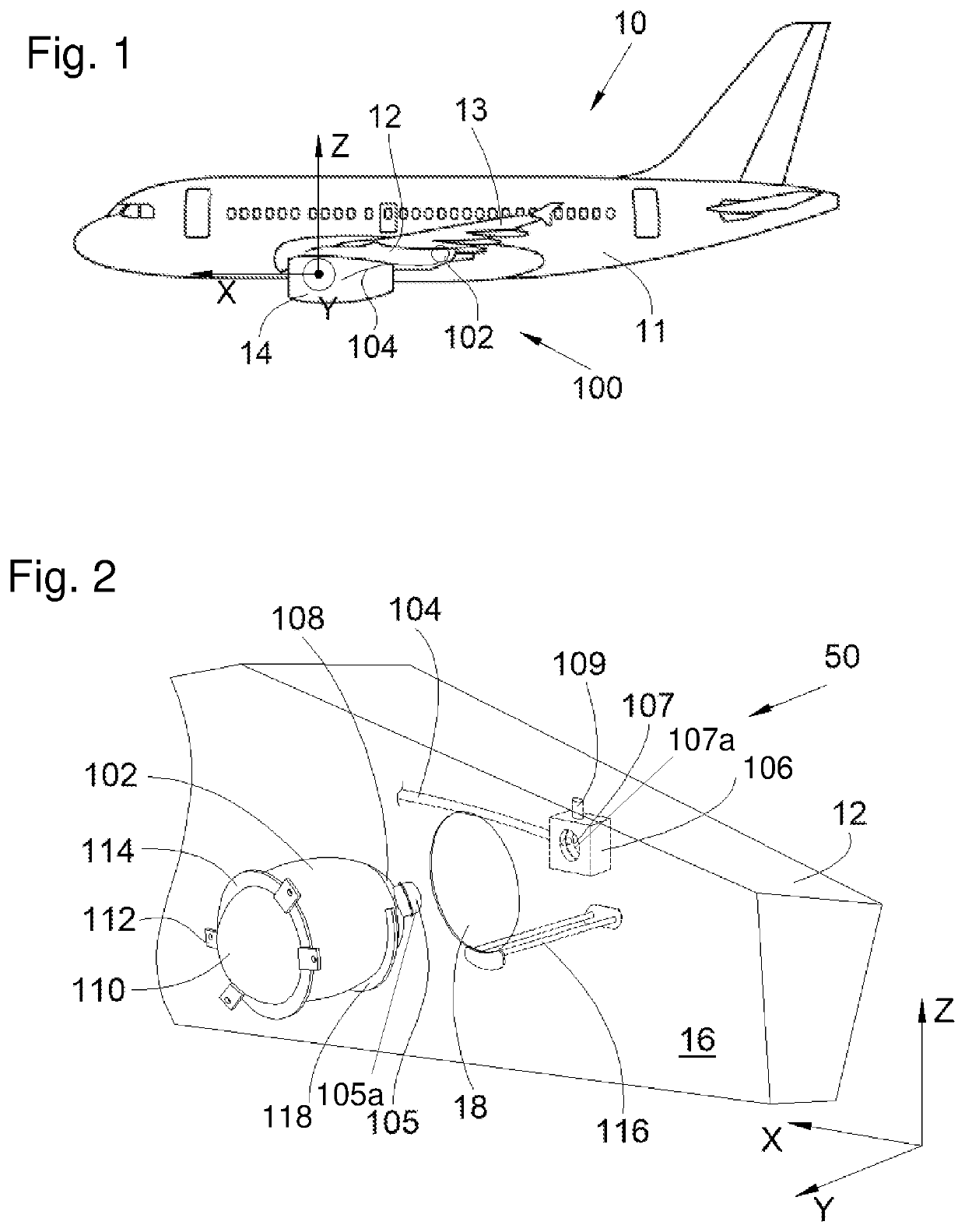
[0026]In the following description, terms relating to a position refer to an aircraft in a normal flight position, that is to say, as represented in FIG. 1.
[0027]In the following description, and by convention, the longitudinal direction of the turbojet which is parallel to the longitudinal axis of the aircraft is named X, the transverse direction which is horizontal when the aircraft is on the ground is named Y, and the vertical direction which is vertical when the aircraft is on the ground is named Z, these three directions X, Y and Z being mutually orthogonal.
[0028]FIG. 1 shows an aircraft 10 that includes a fuselage 11, to each side of which is fixed a wing 13 that carries an engine 14 such as, for example, a turbofan engine.
[0029]The aircraft 10 also includes, for each engine 14, a pylon 12 that fixes the engine 14 under the wing 13.
[0030]The aircraft 10 includes, for each engine 14, an anti-fire system 100 that includes at least one tank 102 and a discharge pipe 104 for each tank 102 that extends between the tank 102 and the engine 14 supported by the pylon 12.
[0031]FIG. 2 and FIG. 3 show an assembly 50 that includes the pylon 12, the tank 102 and the discharge pipe 104.
[0032]The tank 102 is filled with an extinguisher fluid and includes a neck 105 blocked by a film 103 that closes the tank 102 and where the neck 105 carries a first anchoring arrangement 105a.
[0033]The assembly 50 also includes a discharge head 106 to which the discharge pipe 104 is fluidically connected. The discharge head 106 is fixed inside the pylon 12 by any appropriate such as screws, for example. The discharge head 106 includes a hole 107 in which the discharge pipe 104 discharges and the discharge head 106 carries a second anchoring arrangement 107a around the hole 107.
[0034]The second anchoring arrangement 107a around the hole 107 and the first anchoring arrangement 105a on the neck 105 are configured to cooperate with one another to fix the neck 105 to the discharge head inside the hole 107. In accordance with one particular embodiment, the anchoring arrangements take the form of a quarter-turn bayonet or screw-type fixing and the tank 102 is installed on the discharge head 106 by rotation of the neck 105 in the hole 107 and conversely the tank 102 is removed by a reverse rotation of the neck 105.
[0035]The discharge head 106 also includes an explosive cartridge 109 that is designed, when it is activated, to generate in the hole 107 a shockwave sufficient to rupture the film 103 that is housed therein and thus to release the extinguisher fluid contained in the tank 102 in order for the extinguisher fluid to flow into the discharge pipe 104. In accordance with one particular embodiment, the explosive cartridge 109 is disposed in part inside the hole 107.
[0036]The pylon 12 classically extends in a longitudinal direction and has two lateral walls 16, namely a port lateral wall 16 and a starboard lateral wall.
[0037]The lateral wall 16, here the port wall, is pierced by a window 18 that enables access inside the pylon 12 and here is circular.
[0038]The discharge head 106 is disposed in such a manner that when the tank 102 is introduced via the window 18 the hole 107 faces the window 18; when the tank 102 is introduced, the neck 105 is therefore aligned with the hole 107.
[0039]The tank 102 has a first end 108 that bears the neck 105 and a second end 110 symmetrical with respect to the first end 108 (less the neck).
[0040]The tank 102 is equipped with a fixing arrangement 112 that here are disposed on the side of the second end 110. Here the fixing arrangement 112 comprises lugs with bolts that are screwed into the lateral panel 16 through the lugs. The fixing arrangement 112 fixes at least a part of the tank 102 inside the pylon 12 when the tank 102 is in the operating position, in particular, the part bearing the neck 105.
[0041]Installing the tank 102 comprises introducing the first end 108 into the window 18 parallel to a direction of introduction that is substantially parallel to the axis of the hole 107 until the neck 105 reaches the hole 107. Depending on the anchoring arrangement provided, the tank 102 is then moved to lock the first anchoring arrangement 105a with the second anchoring arrangement 107a, in particular here, by rotation to screw the neck 105 into the hole 107 and thus to lock the fixing arrangement 112. The tank 102 is then in the operating position and connected to the discharge pipe 104 via the discharge head 106. Here, the direction of introduction is globally parallel to the transverse direction Y.
[0042]The tank 102 is removed in the reverse manner by unlocking the fixing arrangement 112, here by unscrewing the neck 105 and then removing the tank 102.
[0043]Thus, the installation and removal of the tank 102 are effected in a simple and rapid manner, since it is not necessary to demount either the discharge pipe 104 or the discharge head 106.
[0044]To facilitate placing the tank 102 in the operating position in the pylon 12, the assembly 50 includes rails 116 that are fixed inside the pylon 12 and extend parallel to the direction of introduction. The rails 116 are disposed in line with the lower edge of the window 18. The rails 116 are, for example, fixed to the box section of the pylon 12.
[0045]At the level of the first end 108, the tank 102 includes a disk portion 118 that is fixed around the first end 108 and the exterior edge of which is placed on the rails 116 when the first end 108 is introduced into the window 18. The disk portion 118 then slides in translation on the rails 116 as the tank 102 is pushed inside the pylon 12. The angular extent of the disk portion 118 is such that when the tank 102, and therefore the disk portion 118, are rotated, the exterior edge of the disk portion 118 slides in rotation on the rails 116. The disk portion 118 is coaxial with the neck 105.
[0046]To close the window 18, when the tank 102 is in the operating position, the assembly 50 includes a flange 114 fastened to the tank 102. The flange 114 takes the form of a ring, the axis of which is parallel to the direction of introduction, and the flange 114 is disposed on the side of the second end 110 so that when the tank 102 is in the operating position, the flange 114 bears against the lateral wall 16 and blocks the window 18.
[0047]In the embodiment of the invention shown in FIGS. 2 and 3, the lugs of the fixing arrangement 112 are fixed to the flange 114.
[0048]In the embodiment of the invention described here, when the tank 102 is in place through the window 18, the first end 108 is housed in the pylon 12 and the second end 110 is outside the pylon 12.
[0049]In accordance with one particular embodiment, the tank 102 has a non-spherical shape and an elongate shape of ellipsoid or ovoid type.
[0050]The tank preferably takes the form of an elongate ellipsoid with three half-axes, namely the half-major-axis, the half-mean-axis and the half-minor-axis, where the dimension of the tank along a first half-axis is different from the dimension of the tank along at least one other half-axis.
[0051]The half-major-axis extends parallel to the direction of introduction and here extends parallel to the transverse direction Y, the half-mean-axis extends parallel to the vertical direction Z and the half-minor-axis extends parallel to the longitudinal direction X.
[0052]In the embodiment of the invention shown in FIGS. 2 and 3, the dimension of the tank 102 along the half-mean-axis and the dimension of the tank 102 along the half-minor-axis are equal, and the tank 102 is the shape of a rugby ball.
[0053]This elongate ellipsoid shape makes it possible for the tank 102 to have a greater volume without increasing the maximum diameter of the tank.
[0054]The installation of this kind of tank 102 enables a greater volume of the extinguisher fluid without having to increase the diameter of the window 18 and therefore without risk to the structure of the pylon 12.
[0055]In the embodiment of the invention described hereinabove there is only one tank 102 per pylon 12, but there are preferably at least two tanks 102 per pylon 12. The invention then applies in the same manner to each tank 102 and, in this case, there is a window 18 in each lateral wall 16, namely in the port lateral wall and the starboard lateral wall, and one tank 102 per window 18.
[0056]While at least one exemplary embodiment of the present invention(s) is disclosed herein, it should be understood that modifications, substitutions and alternatives may be apparent to one of ordinary skill in the art and can be made without departing from the scope of this disclosure. This disclosure is intended to cover any adaptations or variations of the exemplary embodiment(s). In addition, in this disclosure, the terms “comprise” or “comprising” do not exclude other elements or steps, the terms “a” or “one” do not exclude a plural number, and the term “or” means either or both. Furthermore, characteristics or steps which have been described may also be used in combination with other characteristics or steps and in any order unless the disclosure or context suggests otherwise. This disclosure hereby incorporates by reference the complete disclosure of any patent or application from which it claims benefit or priority.

PUM

no PUM

Description & Claims & Application Information

We can also present the details of the Description, Claims and Application information to help users get a comprehensive understanding of the technical details of the patent, such as background art, summary of invention, brief description of drawings, description of embodiments, and other original content. On the other hand, users can also determine the specific scope of protection of the technology through the list of claims; as well as understand the changes in the life cycle of the technology with the presentation of the patent timeline. Login to view more.
Why Eureka
Try Eureka