
LED lens array for backlight device and display device having same

Active Publication Date: 2021-06-24
SAMSUNG ELECTRONICS CO LTD
View PDF0 Cites 2 Cited by
  • Summary
  • Abstract
  • Description
  • Claims
  • Application Information

AI Technical Summary

Benefits of technology

The patent text describes a new technology that helps improve the efficiency of solar cells. The technology involves using a special coating on the surface of the solar cell to prevent the reflection of light and enhance the absorption of light. This results in a more effective solar cell that can capture more sunlight and convert it into electrical energy.

Problems solved by technology

As a size of a display device becomes gradually larger, the number of LEDs installed on a printed circuit board increases, an operation of installing an LED lens on each of a plurality of LEDs provided on a printed circuit board has a problem of requiring a lot of man hour.
Also, when a plurality of LED lenses are installed in a plurality of LEDs, there is a problem in that an LED lens may be distorted on the LED.

Method used


Image

  • LED lens array for backlight device and display device having same
  • LED lens array for backlight device and display device having same
  • LED lens array for backlight device and display device having same

Examples


Embodiment Construction

[0046]Embodiments of an LED lens array for a backlight device and a display device including same will be described with reference to the attached drawings.

[0047]Examples described hereinafter are for easy understanding of the disclosure, and it should be understood that various changes can be made to examples described herein and the disclosure can be embodied in different forms. In addition, in the following description, detailed descriptions of well-known functions or configurations will be omitted since they would unnecessarily obscure the subject matters of the disclosure. In addition, it should be noted that the drawings as attached are just for easy understanding of the disclosure, and are not illustrated as really scaled, and dimensions of some elements may be exaggerated.

[0048]Terms such as first and second may be used to describe various components, but the components should not be limited by the terms. The terms may be used only for the purpose of distinguishing one compo...


PUM


Abstract

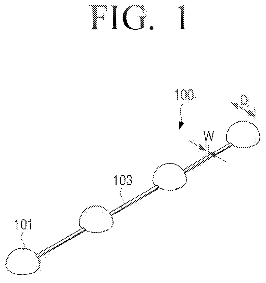
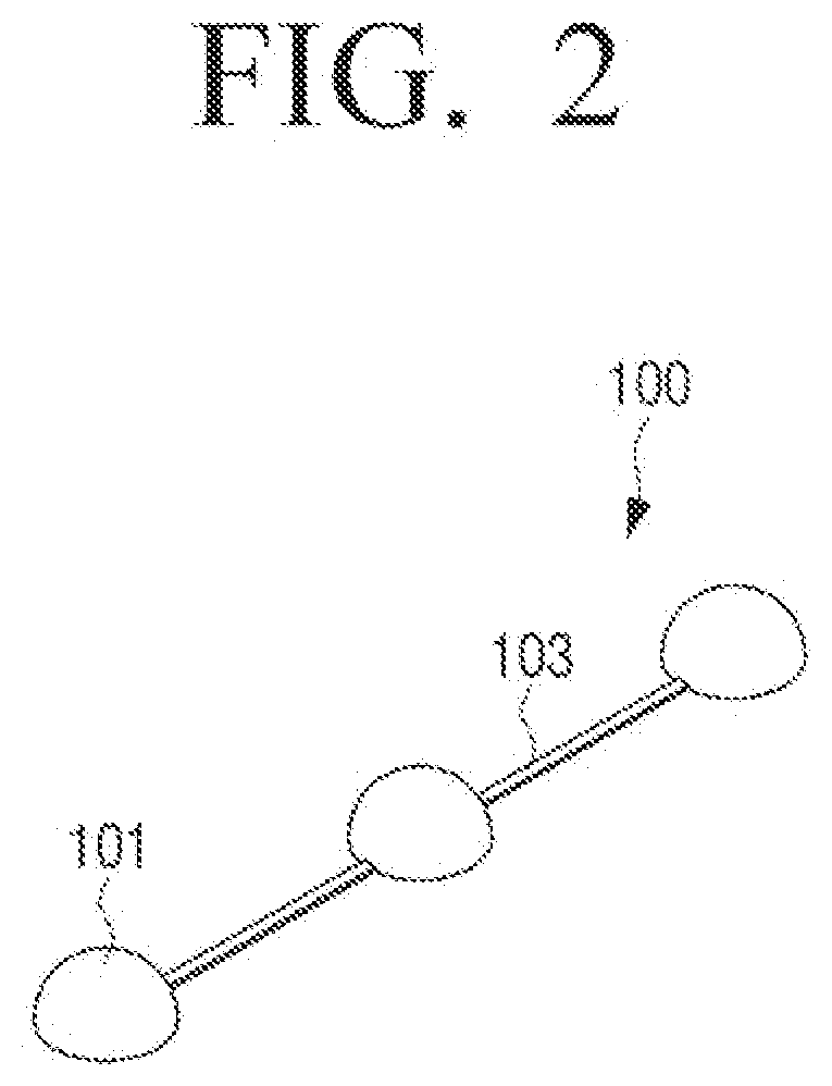
An LED lens array for a direct type backlight device, according to the present disclosure, comprises: a plurality of LED lenses disposed on a plane; and a plurality of lens strings connecting the plurality of LED lenses, wherein each of the plurality of lens strings extends from each side of each of the plurality of LED lenses, and is configured to allow light emitted from each of the plurality of LED lenses to pass therethrough, wherein the width of each of the plurality of lens strings is smaller than the diameter of each of the plurality of LED lenses.

Description

TECHNICAL FIELD[0001]This disclosure relates to a backlight device used for a display device. More particularly, this disclosure relates to a light emitting diode (LED) lens array used for an LED display device.BACKGROUND ART[0002]A liquid crystal display (LCD) used in a display device includes a backlight device which emits light uniformly on a liquid crystal display, since the LCD itself may not emit light.[0003]In general, a backlight device used in a liquid crystal display is classified into an edge type backlight device and a direct type backlight device according to a position of a light source. The edge type backlight device has a light source positioned in one side or both sides of a light guide plate and has a structure for irradiating light into a light guide plate. The direct type backlight device has a structure where a light source is arranged on a lower portion of a diffuser plate to irradiate the light to an overall portion of the diffuser plate.[0004]As a light sourc...

Claims


Application Information

Patent Timeline
IPC IPC(8): G02F1/1335G02F1/13357
CPCG02F1/133607G02F1/133603G02B3/00G02F1/133608G02B3/0006G02B6/0011F21V5/007
Inventor PARK, YEONKYUNLEE, GONGHEEJEON, TAEHEEKIM, JONGSEONGJUNG, YOUNGWOOK
Owner SAMSUNG ELECTRONICS CO LTD
Learn More