
Vehicle roof rack downforce wing

a technology for roof racks and vehicles, applied in vehicle components, vehicle body streamlinings, supplementary fittings, etc., can solve the problems of reducing reducing the efficiency of vehicular rear wings, and vehicle instability in corners, so as to reduce the effectiveness of rear wings, reduce the efficiency of vehicular rear wings, and reduce the effect of air pressur

Inactive Publication Date: 2021-07-01
POLUEKTOV DMYTRO
View PDF0 Cites 0 Cited by
  • Summary
  • Abstract
  • Description
  • Claims
  • Application Information

AI Technical Summary

Benefits of technology

This patent is about adding a downforce wing to a vehicle to improve its performance. Specifically, it describes a roof-mounted downforce wing that is attached to a carrier rack to increase the vehicle's traction on the road. The technical effect is better performance and a more aggressive stance for the vehicle.

Problems solved by technology

As such, downforce wings are typically bolted on and installed in the back due to having convenient, unobtrusive and sturdy location to install on top of the trunk, directly and permanently attached to the vehicular chassis.
However there are some detrimental effects reducing efficiency of vehicular rear wings, primarily due to air turbulence in the back of the vehicular slipstream.
This reduces the effectiveness of the rear wings due to the reduced air pressures applied on them.
Additionally due to the turbulence, the force applied on the rear wings is inconsistent, contributing to vehicle instability in corners.
This is highly undesirable as downforce wings are primarily designed for the purposes of increasing vehicle stability and traction.

Method used


Image

  • Vehicle roof rack downforce wing
  • Vehicle roof rack downforce wing

Examples


Embodiment Construction

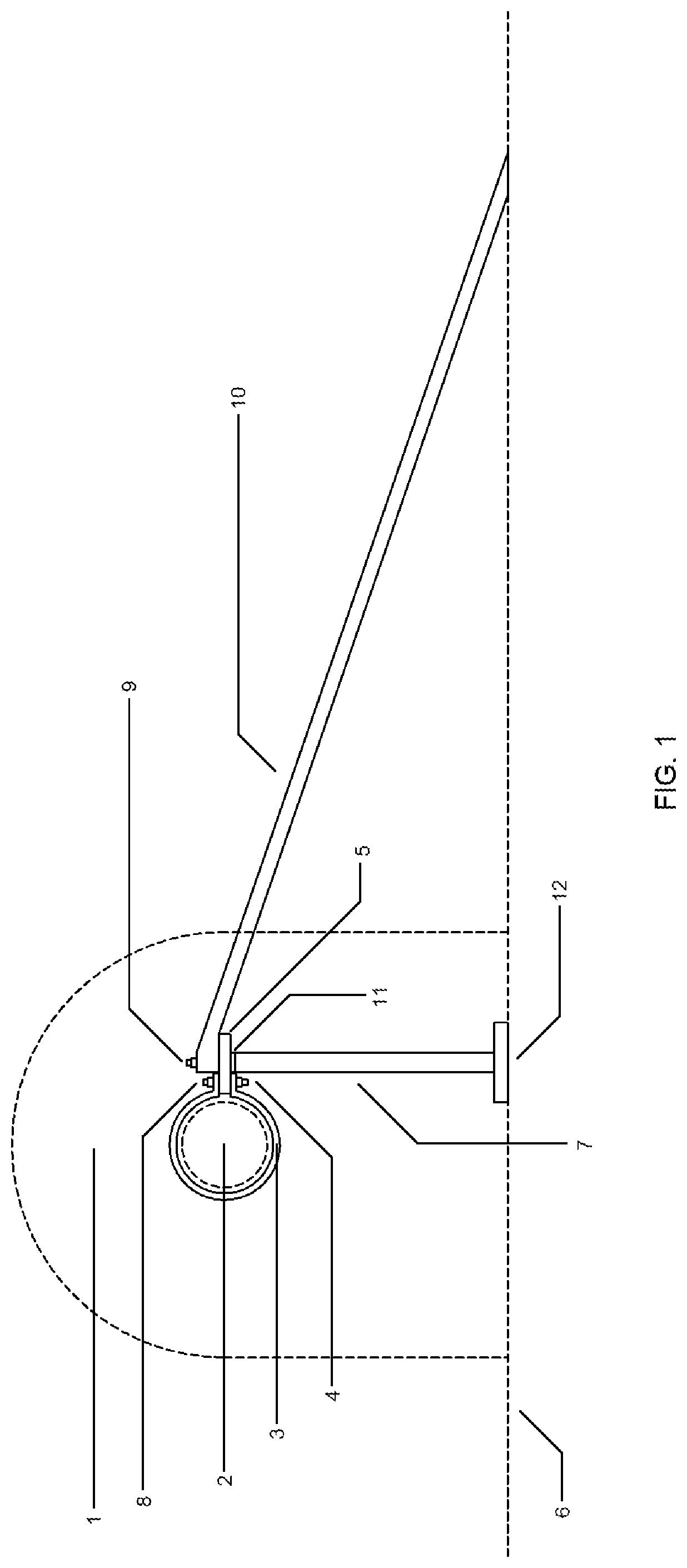
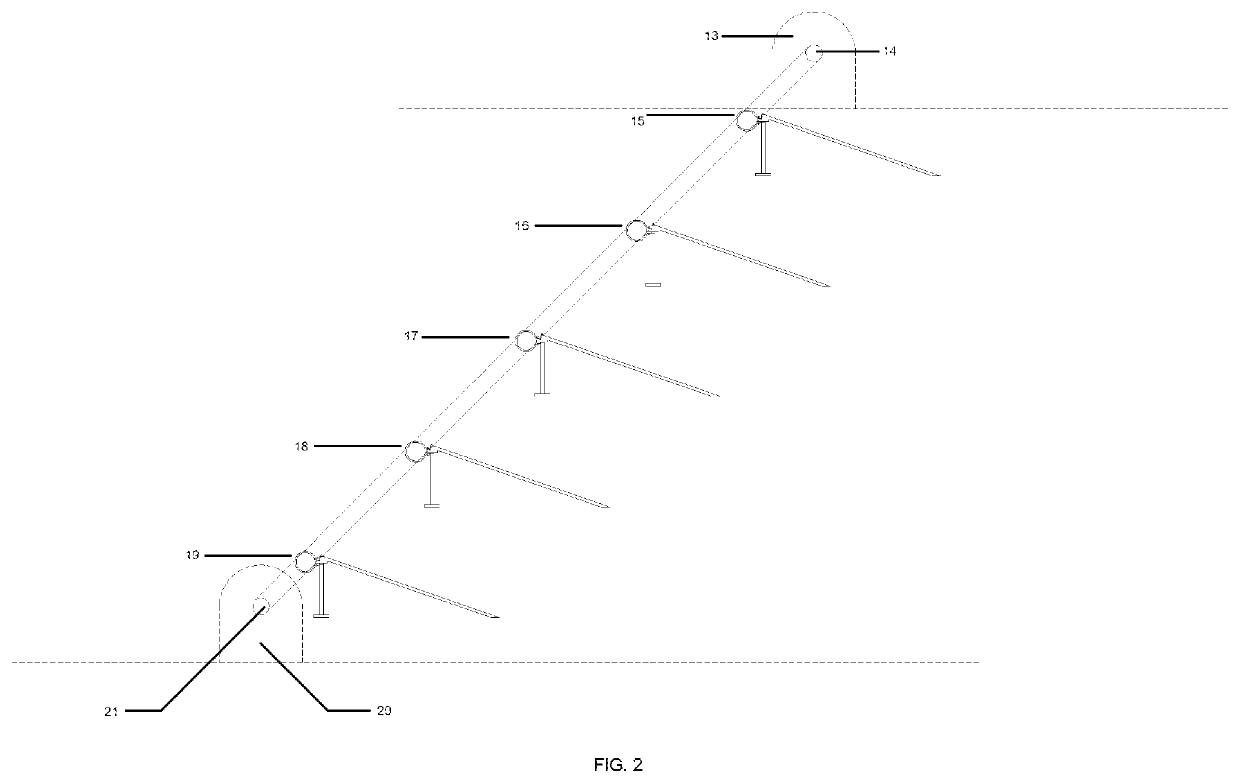
[0009]A sample downforce roof wing installation design in accordance with the present invention is demonstrated in a cutaway FIG. 1. In this figure, the roof downforce wing 10 is shown mounted to the roof rack crossbar on an automobile roof 6. The roof wing is mounted to the automobile roof through the use of a roof rack consisting of roof rack pedestal 1 and roof rack crossbar 2. Specifically, the roof wing is attached to the roof rack crossbar through the use of crossbar clamp 3 mounted on the crossbar. The clamp than connects to the interconnecting plate 5. The interconnecting plate then interconnects the crossbar to the roof wing 10 and the supporting roof pedestal 7. The interconnecting plate is bolted to the crossbar and the roof wing assembly through the use of nut and bolt assemblies with locking washers 4 and 9. The downforce roof wing assembly is composed of the wing 10 and the downforce force support pedestal 7. The downforce support pedestal contacts the automobile roof ...


PUM


Abstract

An downforce wing on a vehicle roof rack is horizontally secured by a set of clamps, each clamp secured independently of each other on a vehicle roof rack crossbar. The downforce wing is vertically secured on its back end by the said clamps' with roof pedestals attached to them, which support the downward force generated by the downforce wing and is vertically secured by the downforce wing roof base itself on its front end. The base size of the downforce wing roof pedestals varies to support downforce wings of various sizes and downward force performance. Should any of the clamps loosen due to a mechanical failure, the remaining clamps will keep securing the downforce wing to the roof rack crossbar.

Description

[0001]This invention relates to to vehicular downforce wing performance accessories and more particular to roof mounted downforce wings attached to automotive carrier racks to increase vehicular downward traction force.BACKGROUND AND SUMMARY OF THE INVENTION[0002]Downforce wings have been commonly manufactured in a wide variety of shapes, depending on a wide variety of vehicles they are installed on. They are most typically mounted directly on top of vehicle trunk to increase the rear traction. It is critical for the downforce wings to be effectively secured to the vehicle body so that will not detach when experiencing high force loads of air resistance under high speed conditions. As downforce wings are designed to produce downforce, the primary force vector exerted on them is primarily downward, however there is also a secondary horizontal force vector component as a byproduct of aerodynamic drag. As such, downforce wings are typically bolted on and installed in the back due to ha...

Claims


Application Information

Patent Timeline
Patent Type & Authority Applications(United States)
IPC IPC(8): B62D35/00
CPCB62D35/00B60R9/05
Inventor POLUEKTOV, DMYTRO
Owner POLUEKTOV DMYTRO
Learn More