Method and system for automatically levelling dropped ceilings, floating floors, pipes or cable trays

a technology of dropping ceilings and dropping pipes, applied in the field of automatic levelling of dropped ceilings, floating floors, pipes or cable trays, can solve the problems of affecting the type of known anchoring devices described above, complicated and expensive operation sequence, and relatively long operating sequence, so as to achieve simple and economic

Active Publication Date: 2021-07-01
AKIFIX SPA
View PDF0 Cites 1 Cited by
  • Summary
  • Abstract
  • Description
  • Claims
  • Application Information

AI Technical Summary

Benefits of technology

The patent text aims to provide a leveling system for anchoring dropped ceilings that is not affected by the problems of previous systems. The goal is to create a simpler and less expensive solution.

Problems solved by technology

Known anchoring devices of the type described above are affected by some drawbacks, which are mainly due to the fact that, when the receiver signals the wrong position of a section bar relative to the ceiling of the building, operators must remove the section bar from the support bracket, rotate the support bracket on the threaded rod, couple the section bar again to the support bracket and control again the position of the section bar by means of the laser level and the receiver.
In other words, the levelling of the plasterboard dropped ceiling relative to the ceiling of the building implies, for the operators involved in the installation of the dropped ceiling, a relatively long, complicated and expensive operating sequence.

Method used


Image

  • Method and system for automatically levelling dropped ceilings, floating floors, pipes or cable trays
  • Method and system for automatically levelling dropped ceilings, floating floors, pipes or cable trays
  • Method and system for automatically levelling dropped ceilings, floating floors, pipes or cable trays

Examples


Embodiment Construction

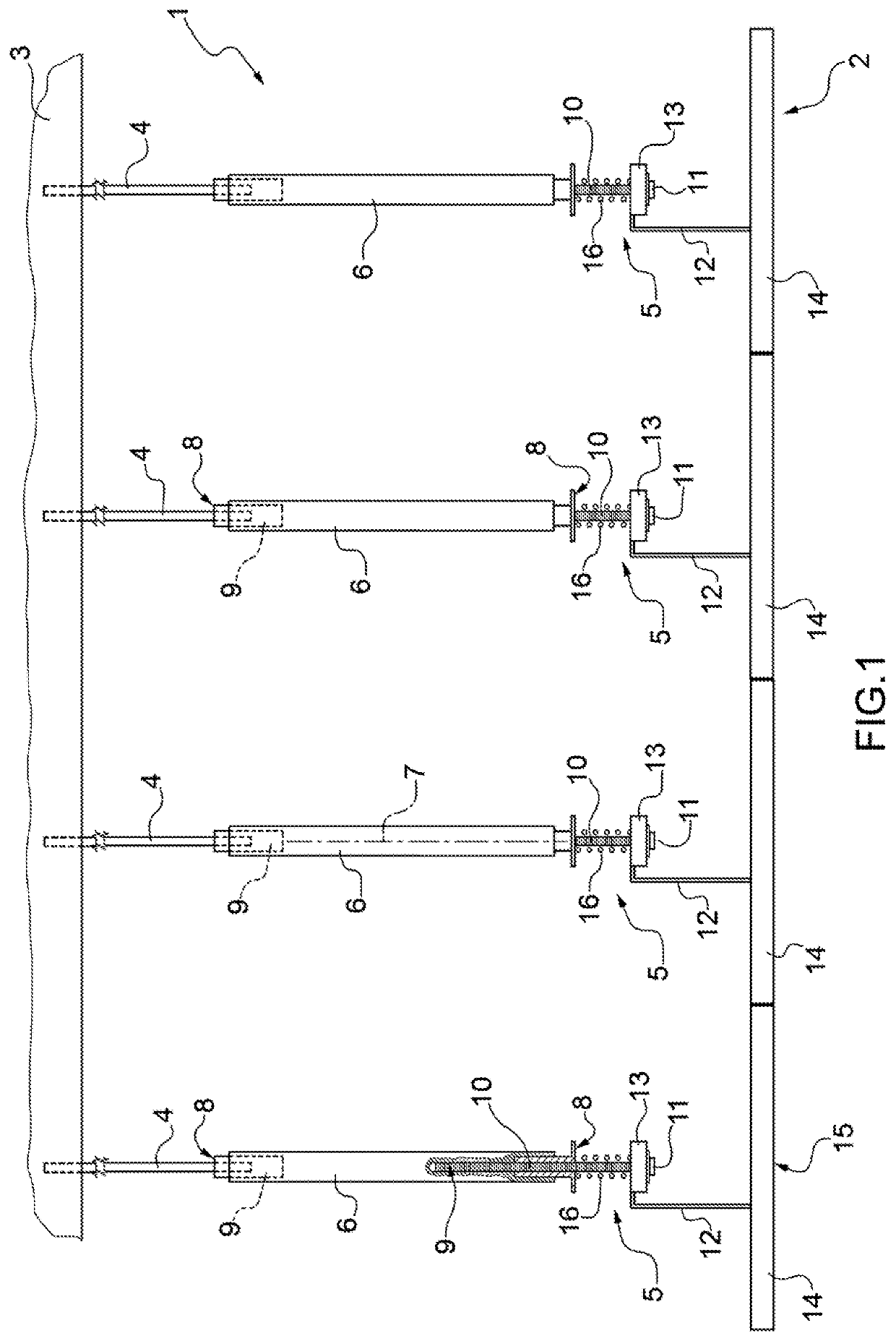
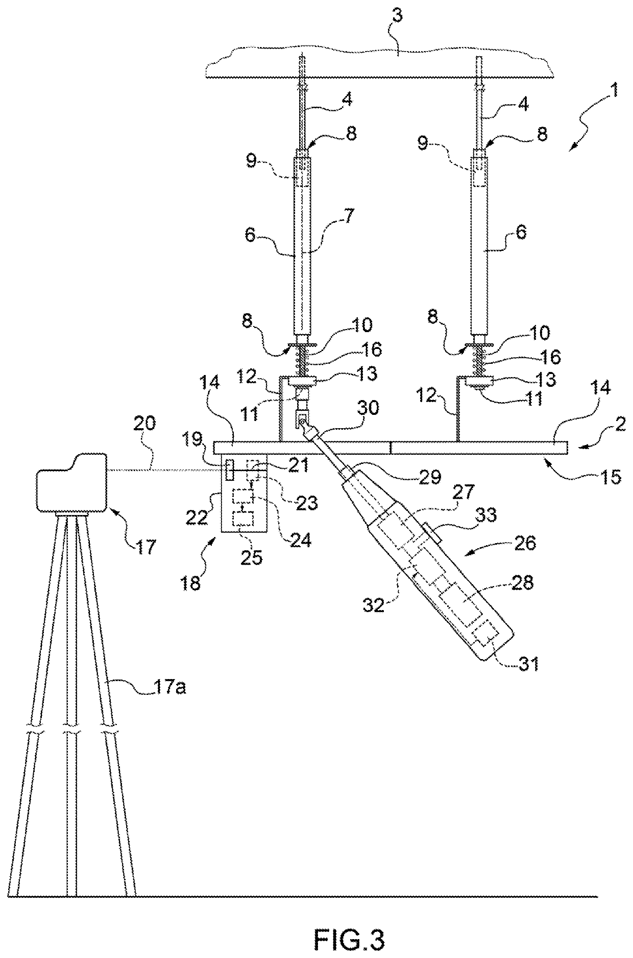
[0017]In FIG. 1, number 1 generically indicates, as a whole, an anchoring system to anchor a dropped ceiling 2, in particular made of plasterboard, to a ceiling 3 of a building. The anchoring system 1 comprises a plurality of hooking rods 4, which are parallel to one another, are coupled to the ceiling 3 in a known manner and project downwards from the ceiling 3.

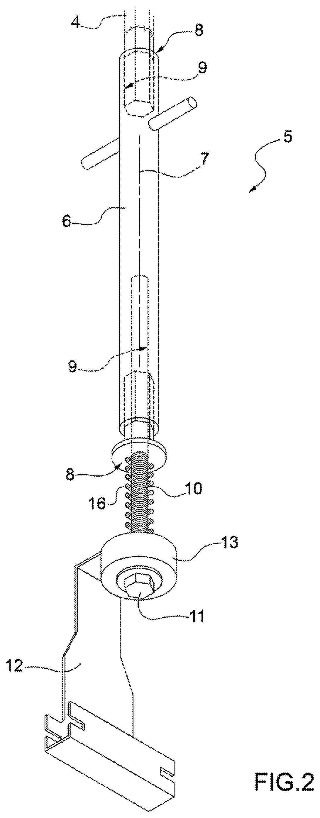
[0018]The anchoring system 1 further comprises, for each hooking rod 4, a respective anchoring device 5 comprising, in turn, a coupling bar 6, which has a longitudinal axis 7 and is axially delimited by two end faces 8, which are substantially perpendicular to the axis 7.

[0019]With reference to FIGS. 1 and 2, the coupling bar 6 has two threaded cavities 9, each opening up outwards in the area of a relative face 8.

[0020]One of the cavities 9 is screwed on a lower threaded end of the hooking rod 4, whereas in the other cavity 9 there is screwed an adjustment screw 10 provided with a hexagonal maneuvering head 11.

[0021]The anch...


PUM


Abstract

A method for levelling an anchoring system for a dropped ceiling, a floating floor, a pipe or a cable tray, having at least one support bracket for the pipe or a section bar of a support frame of a dropped ceiling, a floating floor or a cable tray, and an adjustment screw to adjust the distance of the section bar from a reference surface, wherein a laser receiver is placed in contact with the section bar or the support bracket, has an optical window to receive a laser beam emitted by a laser level, assumes two height states indicating the receiving position of the laser beam relative to a reference position, and transmits, in a wireless manner, two control signals corresponding to the two height states, and wherein an electric screwdriver receives, in a wireless manner, the control signals and switches the rotation of the adjustment screw between one direction and the opposite direction based on the control signal received.

Description

CROSS-REFERENCE TO RELATED APPLICATIONS[0001]This patent application claims priority from Italian patent application no. 102018000005946 filed on Jan. 6, 2018, the entire disclosure of which is incorporated herein by reference.TECHNICAL FIELD[0002]The invention relates to a method for automatically levelling dropped ceilings, floating floors, pipes or cable trays and to a corresponding automatic levelling system.[0003]In particular, the invention finds advantageous, though non-exclusive, application in the automatic levelling of dropped ceilings, to which explicit reference will be made in the description below without because of this losing in generality.BACKGROUND ART[0004]In the building field, an anchoring system is known, which is used to connect a plasterboard dropped ceiling to a ceiling of a building so as to create a hollow space for the passage of a plurality of cables of different types.[0005]The anchoring system comprises a plurality of threaded rods, which are substanti...

Claims


Application Information

Patent Timeline
Patent Type & Authority Applications(United States)
IPC IPC(8): E04F21/18E04F21/20E04F15/024E04B9/20B25B21/00G01C15/00
CPCE04F21/1805E04F21/20G01C15/006E04B9/20B25B21/002E04F15/0247B25F5/00
Inventor PANDOLFI, GIOVANNI
Owner AKIFIX SPA
Why Eureka
Try Eureka