Supercharge Your Innovation With Domain-Expert AI Agents!

Heat recovery ventilator

a ventilator and heat recovery technology, applied in the field of heat exchangers, can solve the problems of material cost and design complexity, wheel effectiveness, pressure drop, etc., and achieve the effect of enhancing thermal energy transfer

Pending Publication Date: 2021-07-01
CARRIER CORP
View PDF0 Cites 0 Cited by
  • Summary
  • Abstract
  • Description
  • Claims
  • Application Information

AI Technical Summary

Benefits of technology

The patent text describes a way to improve the transfer of heat in a device by adding a layer of textured fins. This helps to enhance the transfer of thermal energy.

Problems solved by technology

However, a number of challenges exist for the application of new designs: Wheel effectiveness, pressure drop, material cost and design complexity are some of the key challenges.

Method used


Image

  • Heat recovery ventilator
  • Heat recovery ventilator
  • Heat recovery ventilator

Examples


Embodiment Construction

[0032]A detailed description of one or more embodiments of the disclosed apparatus and method are presented herein by way of exemplification and not limitation with reference to the Figures.

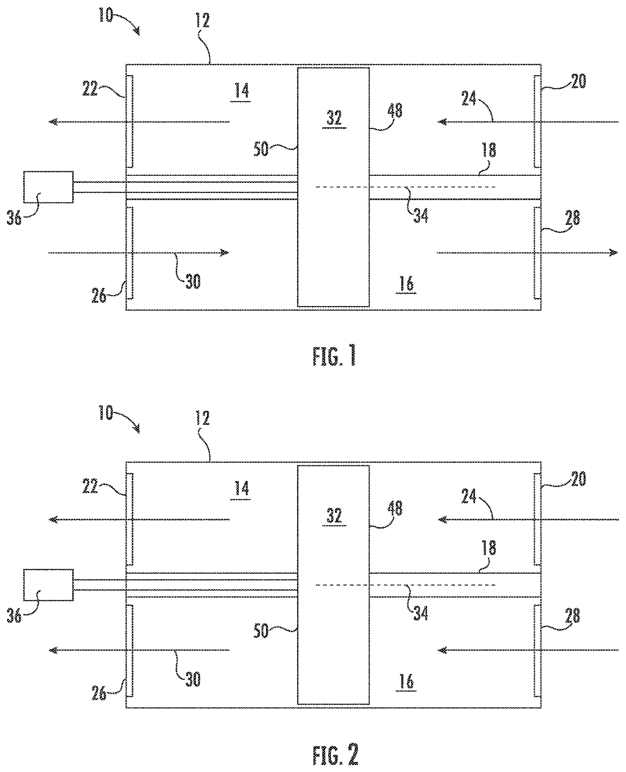
[0033]Referring now to FIG. 1, illustrated is a schematic view of an embodiment of a heat recovery ventilator 10. The heat recovery ventilator 10 includes a housing 12 having a first airflow chamber 14 and a second airflow chamber 16. In some embodiments, the first airflow chamber 14 and the second airflow chamber 16 are separated by an internal housing wall 18. The first airflow chamber 14 includes a first inlet port 20 and a first outlet port 22, through which a first airflow 24 is directed through the first airflow chamber 14. Similarly, the second airflow chamber 16 includes a second inlet port 26 and a second outlet port 28, through which a second airflow 30 is directed through the second airflow chamber 16. In some embodiments, the first airflow 24 is, for example, a return airflow from a c...


PUM

PropertyMeasurementUnit
thermal energyaaaaaaaaaa
shapeaaaaaaaaaa
thermal energy transferaaaaaaaaaa

Abstract

A heat recovery wheel for a heat exchanger includes a wheel rim defining an outer perimeter of the heat recovery wheel, and a plurality of wheel passages located between the wheel rim and the wheel axis. The plurality of wheel passages are at least partially defined by one or more passage fins. At least a portion of a passage fin of the plurality of passage fins extends non-parallel to the wheel axis between a first wheel end and a second wheel end. The plurality of wheel passages are configured for flow of a first airflow and a second airflow therethrough for thermal energy exchange between the first airflow and the second airflow.

Description

BACKGROUND[0001]Exemplary embodiments pertain to the art of heat exchangers, and more particularly to rotary wheel heat recovery ventilators.[0002]Heat exchangers are utilized in ventilation systems installed in, for example, residential, commercial and industrial spaces to extract and remove heat and / or moisture from one airstream and transfer that heat energy and / or moisture to a second airstream. In particular, rotary wheel heat exchangers, or heat recovery ventilators, are known wherein a wheel rotates in a housing through countervailing streams of exhaust and fresh air, in the winter extracting heat and moisture from the exhaust stream and transferring it to the fresh air stream. In the summer rotary wheel heat exchangers extract heat and moisture from the fresh air stream and transfer it to the exhaust stream, preserving building air conditioning while providing desired ventilation.[0003]Heat transfer enhanced heat recovery wheels present an opportunity for the development of ...

Claims


Application Information

Patent Timeline
Patent Type & Authority Applications(United States)
IPC IPC(8): F28D19/04F24F12/00F28F13/12
CPCF28D19/042F24F12/00F28F2245/04F28F2245/02F28F13/12
Inventor ALAHYARI, ABBAS A.HOYSALL, DHRUV CHANAKYA
Owner CARRIER CORP
Features
  • R&D
  • Intellectual Property
  • Life Sciences
  • Materials
  • Tech Scout
  • Unparalleled Data Quality
  • Higher Quality Content
  • 60% Fewer Hallucinations
Learn More