Electronic stun grenade

a technology of electronic stun grenades and casings, which is applied in the direction of hand grenades, weapons, and modifications by conduction heat transfer, etc., can solve the problems of reducing the maximum power output achievable, reducing the amount of energy stored inside the casing, and limited power supply volume, so as to reduce the internal volume of the casing available, the effect of reducing the weight of the stun grenad

Pending Publication Date: 2021-07-01
THE SEC OF STATE FOR DEFENCE IN HER BRITANNIC MAJESTYS GOVERNMENT OF THE UK OF GREAT BRITAIN & NORTHERN IRELAND
View PDF1 Cites 0 Cited by
  • Summary
  • Abstract
  • Description
  • Claims
  • Application Information

AI Technical Summary

Benefits of technology

[0019]Some embodiments of the invention further comprise a light transmissive coating covering at least the means for generating light. The coating is intended to be transmissive to the light generated by the means for generating light. The coating may be an epoxy coating that during manufacture of the electronic stun grenade could be applied and then turned down to the required diameter on a lathe and polished to give a clear transparent finish. The coating may be used to alter the optical properties of the means for generating light. The transmissive coating would provide additional environmental protection.
[0020]According to a second aspect of the invention there is provided a projectile comprising the electronic stun grenade of any preceding claim, wherein the projectile has a maximum diameter substantially equal to 40 mm. The surface mounting of a means for generating light as a result increases the internal volume of the casing available for housing a power supply, without needing to increase the casing diameter (and consequently mitigating an increase in stun grenade weight). The inventor has shown that an electronic stun grenade car be manufactured having a 40 mm diameter that can be used as a projectile launched from a 40 mm grenade launcher.

Problems solved by technology

As a result the volume inside the casing available for a power supply is limited.
This inevitably results in a reduction in the amount of energy storable inside the casing, and consequently either a reduction in peak power output achievable from the means for generating light, or a reduction in operational time.
However this results in a heavier stun grenade owing to the additional weight of the casing, which is undesirable for some applications where weight is a significant constraint (for instance stun grenades that can be launched from grenade launchers).

Method used


Image

  • Electronic stun grenade
  • Electronic stun grenade
  • Electronic stun grenade

Examples


Embodiment Construction

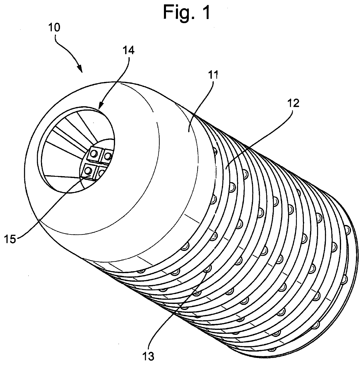
[0025]FIG. 1 illustrates a perspective view of an embodiment of the electronic stun grenade 10. A casing 11 is shown onto which a plurality of electrically conductive bands 12 is mounted. A means for generating light in the form of light emitting diodes 13 is shown attached to electrically conductive bands 12. The casing 11 has a first end 14 in the form of a nose cone. Recessed into the first end 14 is an array of light emitting diodes 15. The casing 11 defines an interior volume suitable for containing a means for powering the light emitting diodes 13. The light emitting diodes 13 are arranged to provide omnidirectional radiation directed away from the casing 13. The light emitting diodes 13 use the 3030 SMD form factor and therefore a variety of different power and wavelength diodes can be used. The light emitting diodes 13 are electrically connected in parallel on each electrically conductive band 12, with the bands themselves being electrically connected in series. The electric...


PUM


Abstract

An electronic stun grenade (10) comprising a casing (11) and a means for generating light (13), wherein the means for generating light (13) is mounted onto an exterior surface of the casing (11). This allows the interior volume defined by the casing (11) to be more effectively used for containing a means for powering the means for generating light (13). Particularly suited to applications requiring compact stun grenades, such as man portable or weapon launched devices.

Description

TECHNICAL FIELD OF THE INVENTION[0001]This invention relates to the field of electronic stun grenades.BACKGROUND TO THE INVENTION[0002]Stun grenades are used by the military and security services, and are also used recreationally in activities such as paintballing. A stun grenade is a device that can be deployed by a user in order to disorient another individual or sensor by saturating their vision with high intensity radiation (light). An electronic stun grenade generates light through use of an electrically powered radiation source. The benefit of an electronic stun grenade is that explosive material is not required in order to generate light, thereby making the stun grenade safer to handle and use. Furthermore the light generated from an electronic stun grenade is more readily controlled with respect to intensity, pulsing, and other effects. Light emitting diodes (LEDs) have been successfully used for this role.[0003]A technical challenge associated with electronic stun grenades ...

Claims


Application Information

Patent Timeline
Patent Type & Authority Applications(United States)
IPC IPC(8): F42B12/42H05K7/20F42B27/00F41H13/00
CPCF42B12/42F41H13/0087F42B27/00H05K7/2039F42B8/18F42B8/20F42B8/26
Inventor COLBOURNE, ROSS
Owner THE SEC OF STATE FOR DEFENCE IN HER BRITANNIC MAJESTYS GOVERNMENT OF THE UK OF GREAT BRITAIN & NORTHERN IRELAND
Why Eureka
Try Eureka