Check patentability & draft patents in minutes with Patsnap Eureka AI!

Pipetting device

Pending Publication Date: 2021-07-01
SOPHONIX CO LTD
View PDF0 Cites 2 Cited by
  • Summary
  • Abstract
  • Description
  • Claims
  • Application Information

AI Technical Summary

Benefits of technology

The patent describes a device for sucking and injecting liquid. It includes a bearing device that moves up and down to allow the feed pump to enter the liquid suction and injection areas. The device is precise and highly automated. It also has a mechanism that removes the tip head to prevent cross-infection after use. This patent aims to provide a reliable and efficient solution for liquid injection in laboratory settings.

Problems solved by technology

The traditional pipetting device generally includes a pipetting sleeve based on the principle of an injection pump, a piston rod is arranged in the pipetting sleeve, pipetting is performed by manually pushing the piston rod, such a working mode is low in working efficiency, and low in liquid suction and injection precision.
In the pipetting device, debugging is tedious in the assembling process of the feed pump, and the maintenance is laborious and time-consuming.
When a plurality of pipetting channels work simultaneously, the piston rods and pipetting sleeves cannot be well matched, and the phenomena that multiple pairs of piston rods and pipetting sleeves are inconsistent in the working process and the piston rods and the pipetting sleeves are jammed easily occur, and the feeding precision and accuracy are affected.

Method used


Image

  • Pipetting device
  • Pipetting device
  • Pipetting device

Examples


Embodiment Construction

[0036]The present application is further illustrated in detail in combination with the accompanying drawings hereinafter.

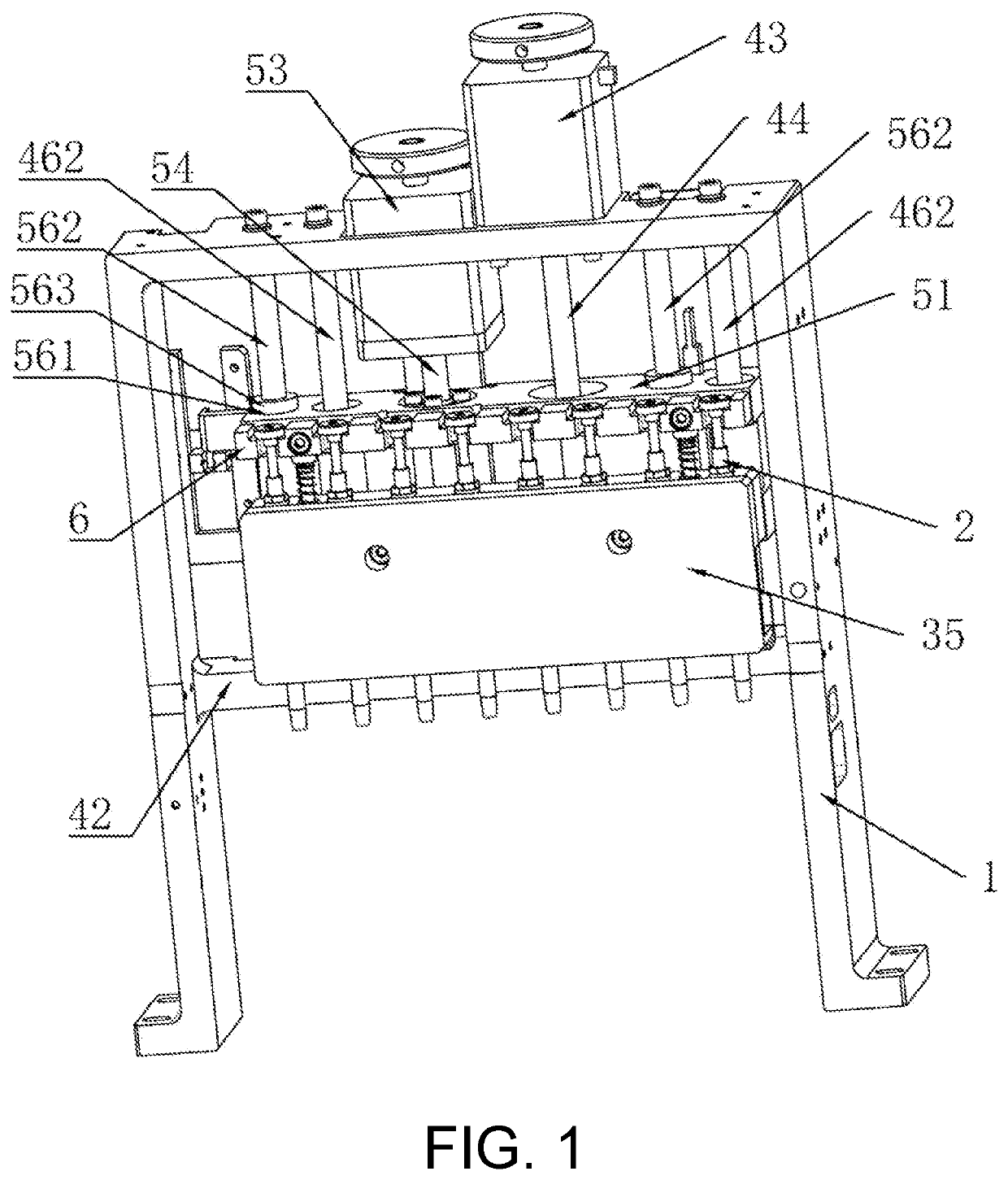
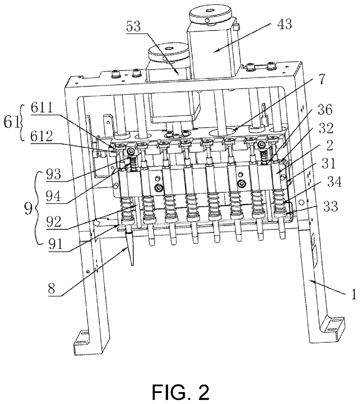
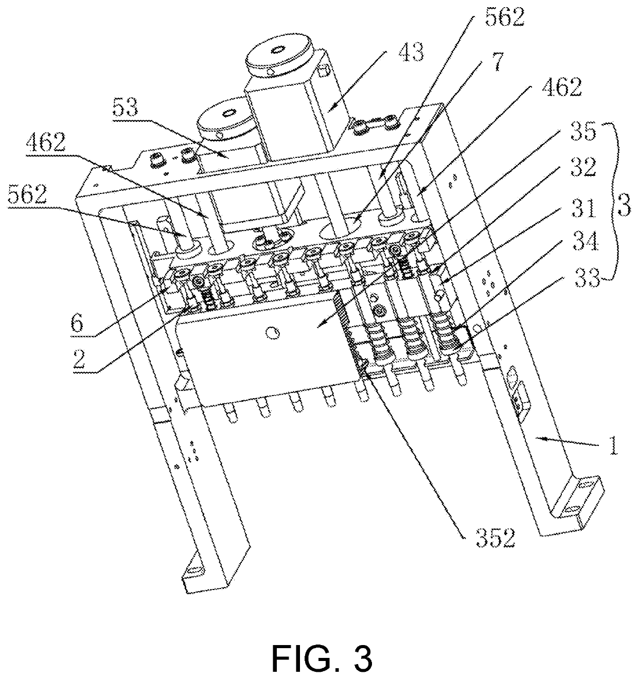
[0037]As shown in FIG. 1 to FIG. 6, there is provided a pipetting device, which includes a portal frame 1. The portal frame 1 is arranged with a bearing device 3 for bearing a feed pump 2, a driving mechanism 5 for driving the bearing device 3 to move up and down and a liquid suction and injection mechanism 5 for sucking or injecting liquid by the feed pump 2.

[0038]The bearing device 3 includes a bearing plate 31 horizontally arranged in the frame 1, and a front side of the bearing plate 31 is formed with a plurality of vertical receiving grooves 32 with front openings. Each of the receiving grooves 32 is embedded with a feed pump 2, an upper end of a feed pipe of the feed pump 2 is arranged with a barrier 33, and the feed pump 2 between the barrier 33 and the bearing plate 31 is sleeved with an elastic member 34. The front side of the bearing plate 31 is fixedly ...


PUM


Abstract

A pipetting device includes a portal frame. The portal frame is arranged with a bearing device for bearing a feed pump, a driving mechanism for driving the bearing device to move up and down, and a liquid suction and injection mechanism for sucking or injecting liquid by the feed pump. The bearing device includes a bearing plate with receiving grooves. The driving mechanism includes a first bracing plate connected to the bearing plate, and the frame is arranged with a first motor. The liquid suction and injection mechanism includes a second bracing plate. The first bracing plate is arranged with a second motor. The first motor and the second motor are connected to a PLC.

Description

CROSS-REFERENCE TO RELATED APPLICATION[0001]The present application is a continuation of international application of PCT application No. PCT / CN2020 / 104908 filed on Jul. 27, 2020, which claims the priority benefit of China application No. 201911104220.8 filed on Nov. 9, 2019. The entirety of each of the above-mentioned patent application is incorporated herein by reference and made a part of this specification.BACKGROUNDTechnical Field[0002]This application relates to the technical field of medical devices, and more particularly, to a pipetting device.Description of Related Art[0003]A pipetting device is widely used in biochemical research laboratories, hospitals, and pharmaceutical companies, and can be used for sample pretreatment, sample purification and amplification, sample dilution and concentration, sample preparation and other sample treatment operations, and generally comprises a pipetting sleeve, a piston rod, an insertion nozzle and the like. When the liquid is sucked, th...

Claims


Application Information

Patent Timeline
IPC IPC(8): G01N1/14G01N35/10
CPCG01N1/14G01N35/1065G01N35/1009G01N35/1016
Inventor HAN, KUILIANGZHOU, SHILIANGZHANG, HAIYANGLI, GUANGHAO
Owner SOPHONIX CO LTD
Features
  • R&D
  • Intellectual Property
  • Life Sciences
  • Materials
  • Tech Scout
  • Unparalleled Data Quality
  • Higher Quality Content
  • 60% Fewer Hallucinations
Learn More