

Computer system and method for determining of resource allocation
- Summary
- Abstract
- Description
- Claims
- Application Information
AI Technical Summary
Benefits of technology
Problems solved by technology
Method used
Image


Examples
first embodiment
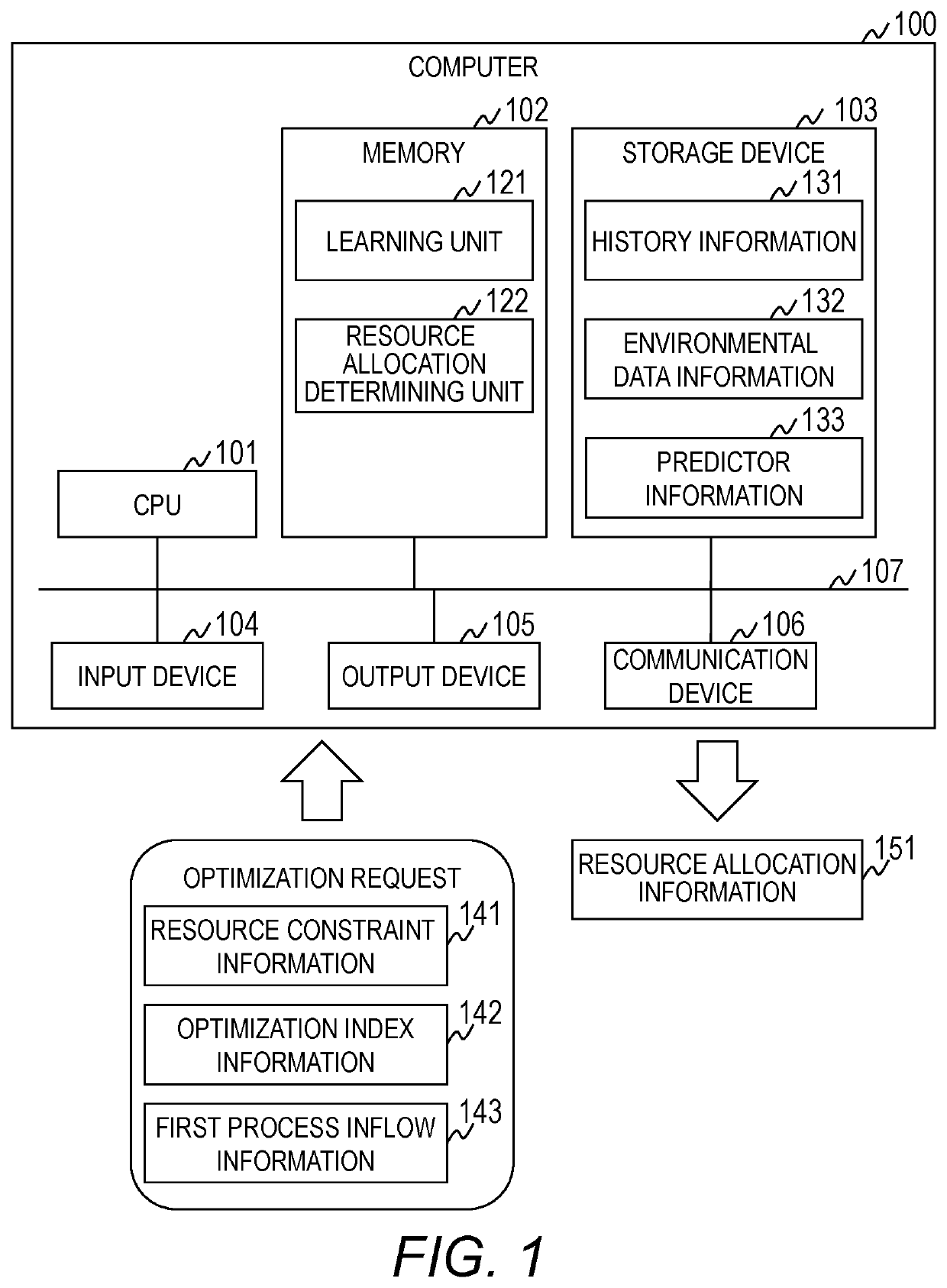
[0030]FIG. 1 is a diagram for illustrating an example of a configuration of a computer 100 in a first embodiment of this invention. FIG. 2 is a diagram for illustrating an example of a task in the first embodiment.
[0031]The computer 100 is configured to determine, based on constraint conditions, an optimal allocation of resources in a task formed of a plurality of processes for processing items. More specifically, the computer 100 is configured to determine an allocation of the resources to each process so that an index serving as an object of the task is optimal, based on constraint conditions relating to the resources.
[0032]Herein, description is given of embodiments while a case in which persons are treated as the resources is exemplified. Facilities may be treated as the resources. Moreover, this invention can also be applied to a case in which an allocation of resources of different types, such as the persons and the facilities, are determined. Further, this invention can also ...
second embodiment
[0125]A second embodiment of this invention is different from the first embodiment in that a predictor configured to predict the inflow amount of the items of the first process is to be generated. Description is now given of the second embodiment while focusing on the difference from the first embodiment.
[0126]The hardware configuration and the software configuration of the computer 100 in the second embodiment are the same as those in the first embodiment. However, the optimization request in the second embodiment does not include the first process inflow information 143.
[0127]In the second embodiment, the predictor configured to predict the inflow amount of the items is generated by the processing described with reference to FIG. 9B for each process other than the first process. The following processing is executed for the first process.
[0128]FIG. 11 is a flowchart for illustrating an example of leaning processing executed by the learning unit 121 in the second embodiment.
[0129]Th...
third embodiment
[0135]A third embodiment of this invention is different from the first embodiment in that the predictors generated by the learning unit 121 are not linear functions. Description is now given of the third embodiment while focusing on the difference from the first embodiment.
[0136]The hardware configuration and the software configuration of the computer 100 in the third embodiment are the same as those in the first embodiment.
[0137]A flow of processing executed by the learning unit 121 in the third embodiment is the same as those in the first embodiment and the second embodiment, but is different in predictors to be generated. For example, the predictors are generated as non-linear functions. For example, in a case where the learning unit 121 generates the predictor of the first process in the third embodiment, a state space model, for example, a particle filter, is used. Alternatively, for example, a probability model that adds disturbance, for example, is generated as the predictor....
PUM
 Abstract
Description
Claims
Application Information