Ignition device

Active Publication Date: 2021-07-01
DIAMOND&ZEBRA ELECTRIC MFG CO LTD
View PDF1 Cites 1 Cited by
  • Summary
  • Abstract
  • Description
  • Claims
  • Application Information

AI Technical Summary

Benefits of technology

The invention allows for more efficient winding and connection of parts in a primary coil, while also preventing an increase in the weight or volume of the entire coil. This is achieved by stacking a main primary coil and an auxiliary primary coil on top of each other, each formed by winding a single primary conductor on a primary bobbin. Essentially, the invention ensures efficient and efficient winding and connection of parts in a primary coil.

Problems solved by technology

This complicates work including winding and connection to each part, causing a risk of reduction in working efficiency.
This further causes a risk of increase in weight or volume of the primary coil (100A) in its entirety.

Method used


Image

  • Ignition device
  • Ignition device
  • Ignition device

Examples


Embodiment Construction

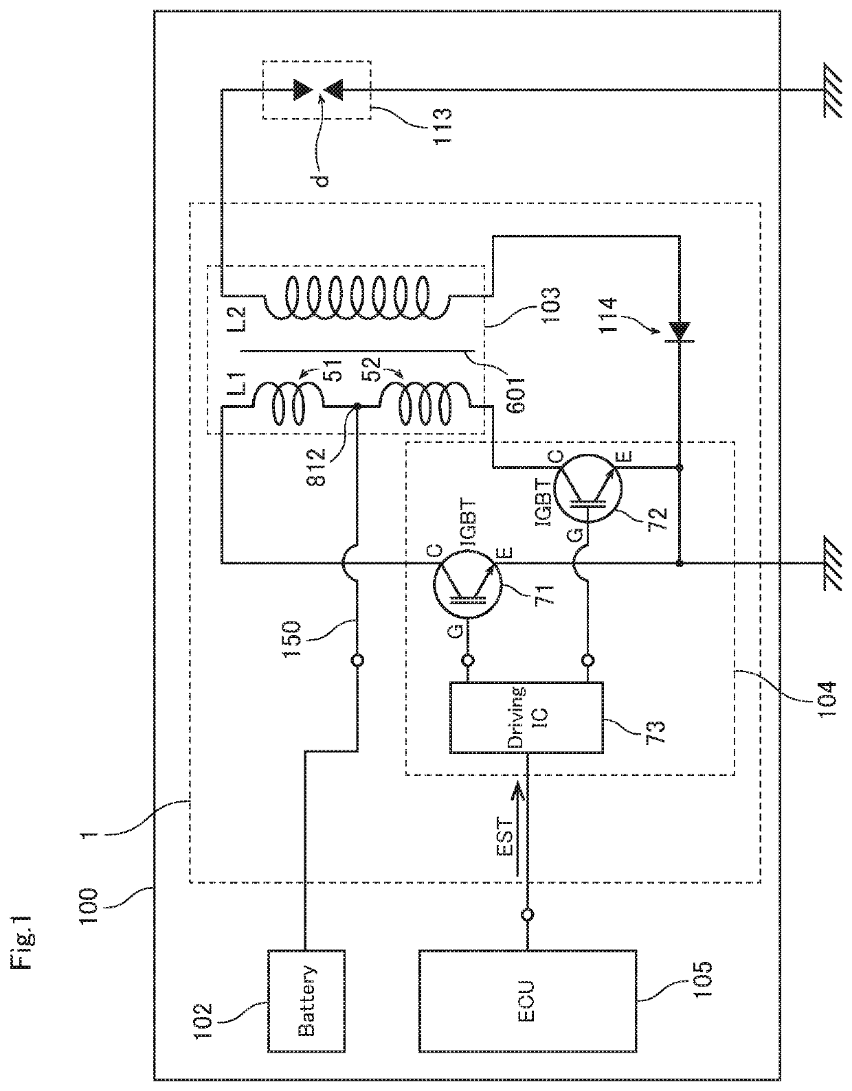
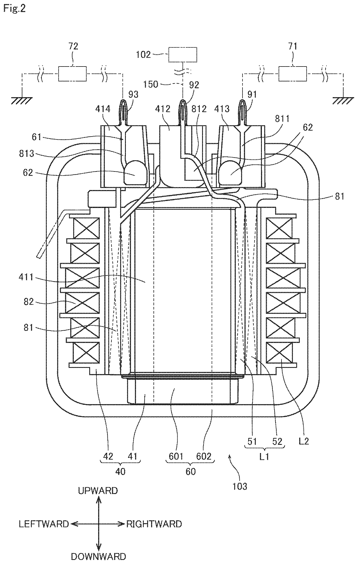
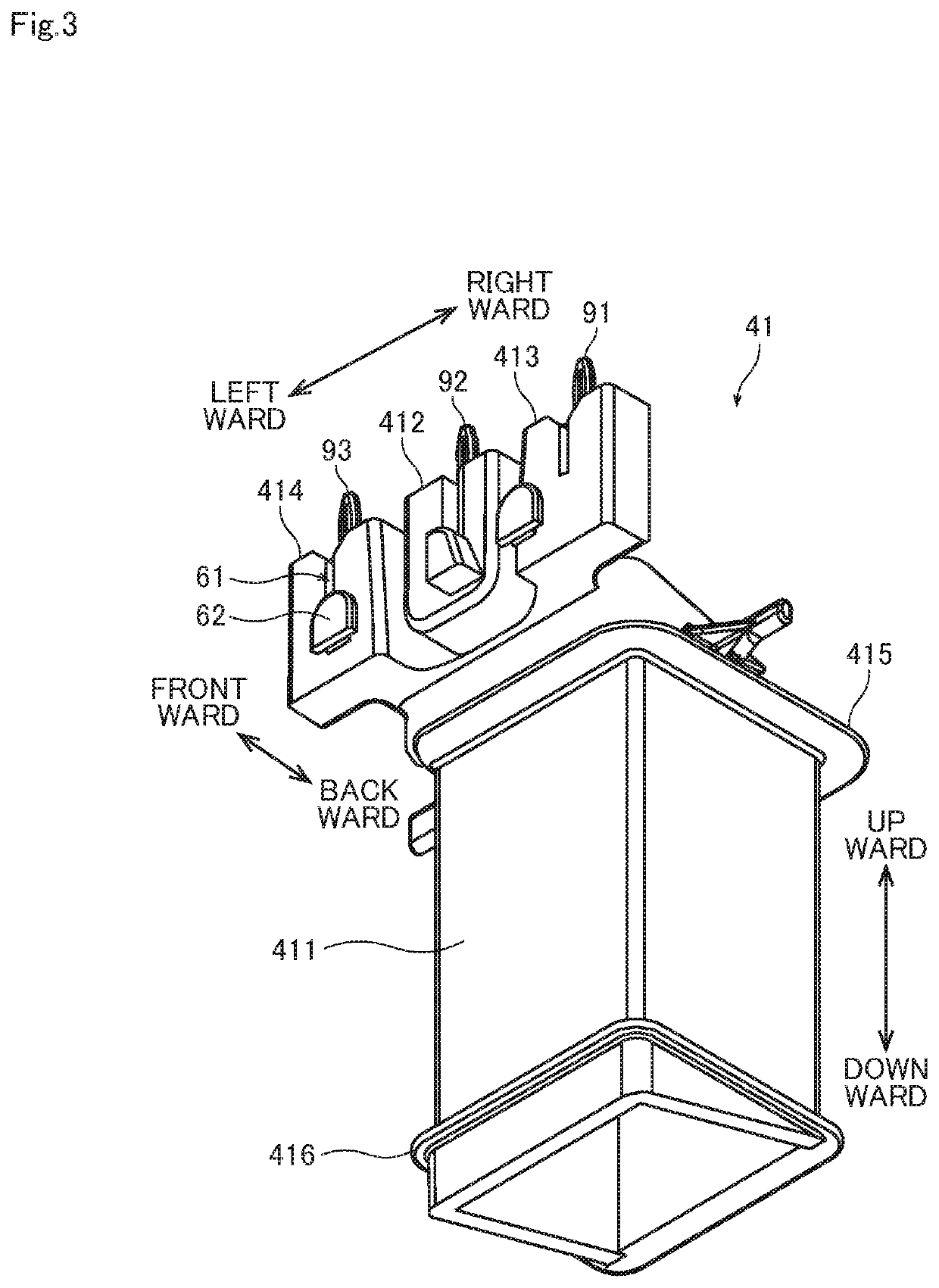
[0019]An exemplary preferred embodiment of the present invention will be described below by referring to the drawings. In the present invention, a direction parallel to the center axis of a bobbin body on which a main primary coil and an auxiliary primary coil in a coil unit described later are wound will be called an “axis direction,” a direction perpendicular to the center axis of the bobbin body will be called a “radial direction,” and a direction along an arc centered on the center axis of the bobbin body will be called a “peripheral direction.” In the present invention, for the convenience of description, the shape of each part and the positions of parts relative to each other will be described while the axis direction is defined as an up-down direction, and a protrusion side where an end of a main primary coil and an end of an auxiliary primary coil are tied is defined as an upper side relative to the bobbin body. However, this definition of the up-down direction is not intend...


PUM


Abstract

An ignition device includes a coil unit and an igniter. The coil unit includes a primary coil and a secondary coil. The primary coil includes a main primary coil and an auxiliary primary coil formed by winding a single primary conductor on a primary bobbin. The secondary coil is formed by winding a secondary conductor on a secondary bobbin. A DC voltage is applied to an intermediate section of the primary conductor between the main primary coil and the auxiliary primary coil. The igniter controls current flowing into the main primary coil or the auxiliary primary coil. The primary bobbin includes a bobbin body and a hooking part protruding from the bobbin body. The main primary coil and the auxiliary primary coil are wound on an outer peripheral surface of the bobbin body to the same direction. A part of the intermediate section is hooked on the hooking part.

Description

RELATED APPLICATIONS[0001]This application claims the benefit of Japanese Application No. 2019-237952, filed on Dec. 27, 2019, the disclosure of which is incorporated by reference herein.BACKGROUND OF THE INVENTIONField of the Invention[0002]The present invention relates to an ignition device for use in an internal combustion engine.Description of the Background Art[0003]A vehicle body such as that of an automobile is conventionally provided with an ignition device for use in an internal combustion engine. The coil unit of the ignition device increases a DC low voltage supplied from a battery to as high as some thousands of volts under control by an engine control unit (ECU), and supplies the increased voltage to a spark plug. By doing so, an electric spark is generated to ignite fuel. An example of the conventional ignition device is disclosed in Japanese Patent No. 6448010, for example.[0004]Japanese Patent No. 6448010 discloses an ignition device (1) for use in an internal combus...

Claims


Application Information

Patent Timeline
IPC IPC(8): H01T15/00H01F38/12H01F27/32
CPCH01T15/00H01F27/325H01F38/12H01F3/10H01F27/29F02P3/02F02P13/00F02P3/0442
Inventor SHONO, ATSUSHIOSHIUMI, HIROSHINISHIMURA, TAKUSHI
Owner DIAMOND&ZEBRA ELECTRIC MFG CO LTD
Why Eureka
Try Eureka