Transmission housing, and wheeled vehicle comprising a housing of this type

Pending Publication Date: 2021-07-08
FRANCE REDUCTEURS SA
View PDF3 Cites 0 Cited by
  • Summary
  • Abstract
  • Description
  • Claims
  • Application Information

AI Technical Summary

Benefits of technology

The invention provides a transmission housing with the following technical effects: simple design reducing parts and assembly ease in factory, easy insertion of output shaft into housing, preventing direct contact between output shaft and housing, simplifying seal-tightness and mounting of shaft inside housing, and easy dismantling of output shaft from transmission housing.

Problems solved by technology

However, it is characterized by a high number of parts which means that its assembly in the factory is difficult and takes a long time.
Furthermore, because of the current design of the transmission housings, it is not generally possible to insert the output shaft in the closed state of the housing.
Indeed, such an output shaft supports a large number of parts which are not held inside the housing, in the absence of the output shaft.

Method used


Image

  • Transmission housing, and wheeled vehicle comprising a housing of this type
  • Transmission housing, and wheeled vehicle comprising a housing of this type
  • Transmission housing, and wheeled vehicle comprising a housing of this type

Examples


Embodiment Construction

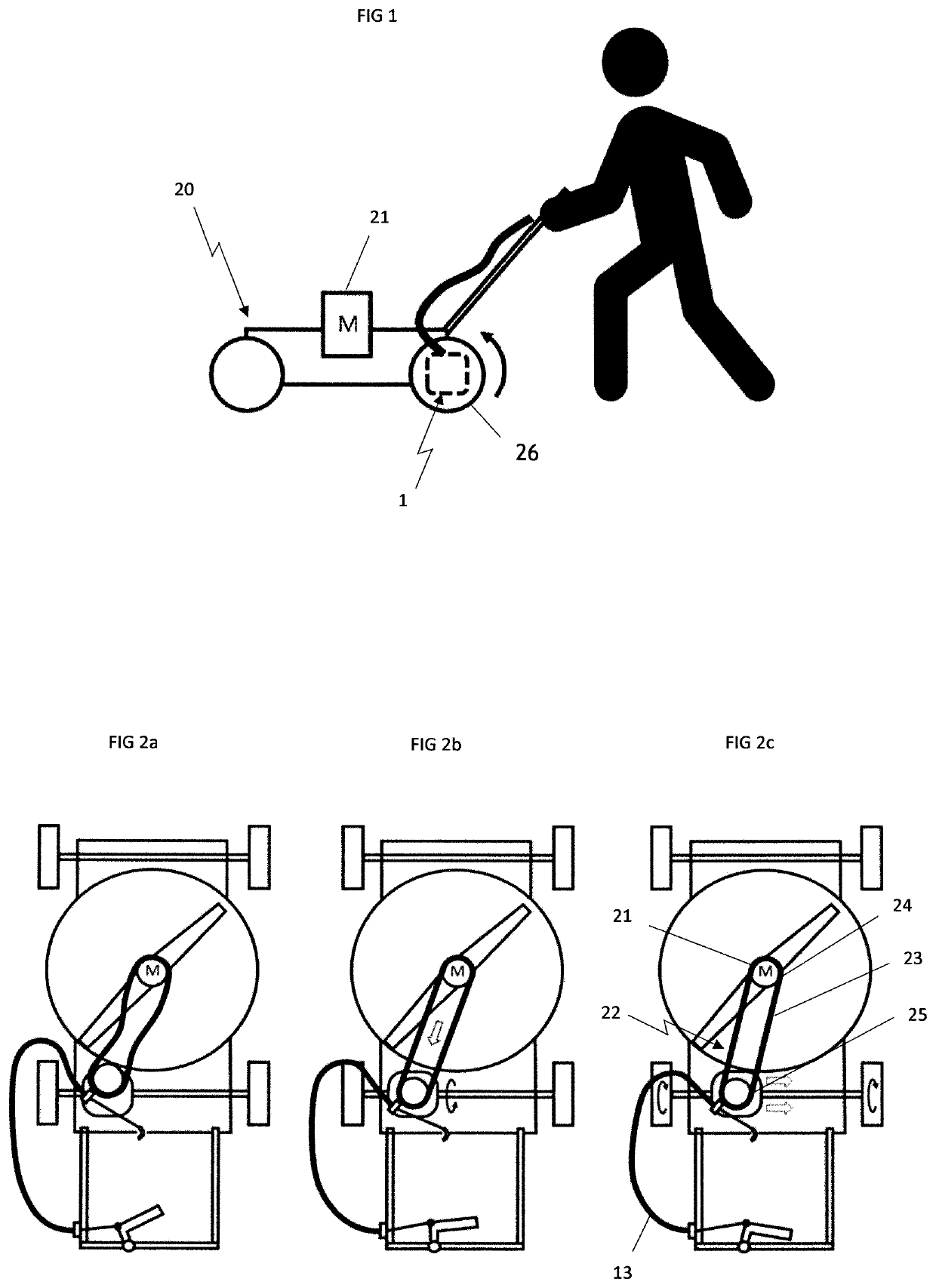
[0033]As mentioned above, the invention relates to a transmission housing 1 intended to be installed on a wheeled vehicle 20 to allow the wheels 26 of the vehicle 20 to be driven in rotation from the motor 21 with which said vehicle is equipped.

[0034]The transmission housing 1 is therefore generally disposed on the shaft driving the wheels 26 of the vehicle 20 in rotation, as represented in FIG. 1, this shaft being called hereinbelow the output shaft 3 of the transmission housing 1.

[0035]The wheeled vehicle 20 is here a lawn mower, but the invention can be applied to other types of wheeled vehicles, notably with the driver walking behind the vehicle 20.

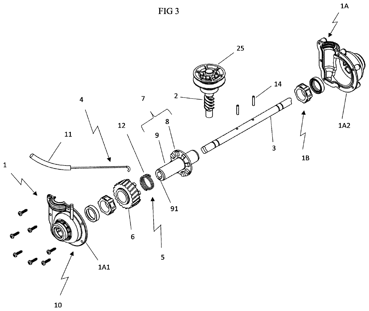
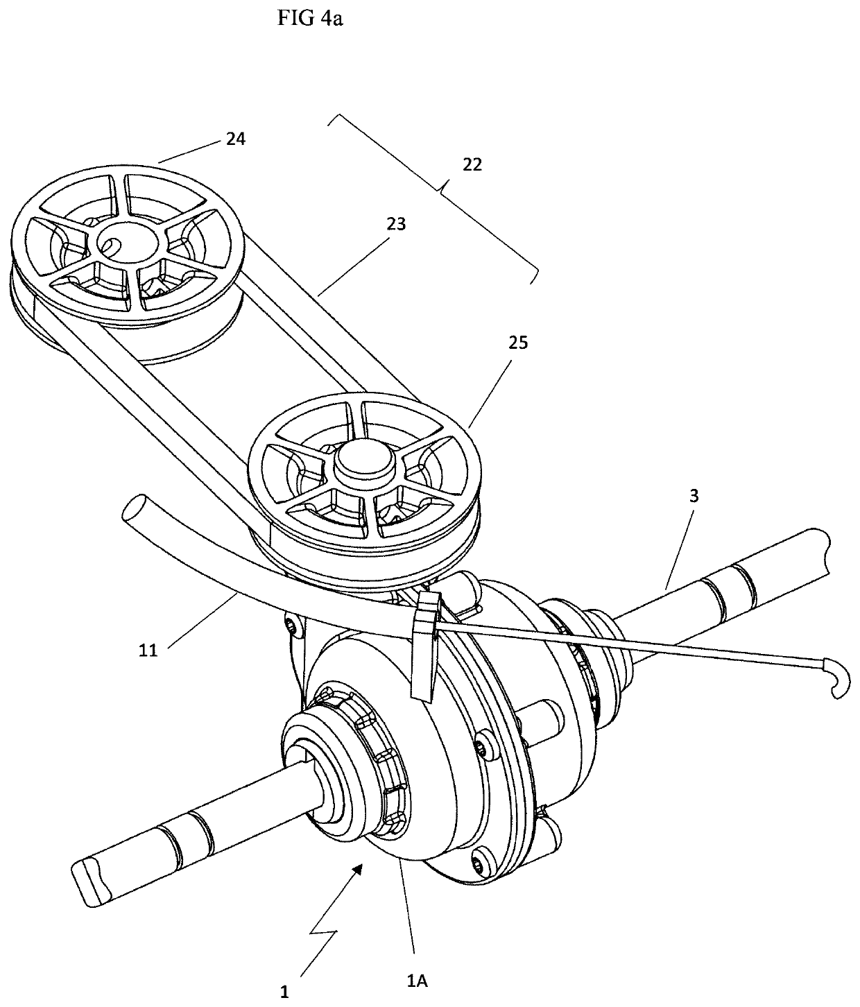
[0036]The transmission housing 1 comprises a housing body 1A delimiting an enclosure 1B. This housing body 1A is, in the example represented, formed by two shells 1A1, 1A2 joined to one another. The joining zone at which the shells 1A1, 1A2 are joined to one another by bonding and / or screwing or other means is called joint plane.

[0037...


PUM


Abstract

The invention relates to a transmission housing (1) comprising a housing (1) body (1A) which defines an enclosure (1B) and, arranged at least partly inside said enclosure (1B), an input shaft (2), an output shaft (3) and a mechanism (4) for transmitting the movement of the input shaft (2) to the output shaft (3), this movement transmitting mechanism (4) comprising at least one clutch (5), the clutch (5) comprising a driving element (6) and a driven element (7), the driven element (7) being mounted for conjoined rotation with the output shaft (3) and comprising an active part (8) of the clutch (5) and a sleeve (9) that carries said active part (8) of the clutch (5), wherein the active part (8) of the clutch (5) is in bearing contact with the driving element (6) of the clutch (5) when the clutch (5) is in the engaged position, the sleeve (9) being coaxial to the output shaft (3) and mounted for conjoined rotation with the output shaft (3), the sleeve (9) of the driven element (7) being made in a single piece with the active part (8) of the driven element (7), and the sleeve (9) being disposed between the output shaft (3) and the body (1A) of the housing (1).

Description

FIELD OF THE INVENTION[0001]The invention relates to a transmission housing and a wheeled vehicle equipped with such a housing.[0002]It relates more particularly to a transmission housing comprising a housing body delimiting an enclosure and, disposed at least partially inside said enclosure, an input shaft, an output shaft and a mechanism for transmitting the movement of the input shaft to the output shaft, this movement transmission mechanism comprising at least one clutch, the clutch comprising a driving element and a driven element, the driven element being mounted to be secured in rotation to the output shaft, at least one of the driven or driving elements of the clutch being mounted to be able to be displaced for the driving and driven elements of the clutch to switch from a position separated from one another corresponding to the declutched position of the clutch to a position close to one another corresponding to the clutched position of the clutch, the driven element of the...

Claims


Application Information

Patent Timeline
IPC IPC(8): A01D34/69A01D34/68
CPCA01D34/69A01D2034/6837A01D34/6812F16D11/14B60K17/02F16D13/26
Inventor TEILLET, EMMANUELMORAND, DAMIEN
Owner FRANCE REDUCTEURS SA
Why Eureka
Try Eureka