
Filter assembly for plate heat exchangers and method of cleaning a working medium in a plate heat exchanger

a filter assembly and plate heat exchanger technology, applied in the field of plate heat exchangers, can solve the problems of affecting the cleaning effect of the working medium, and requiring additional space in the module setting, so as to achieve the effect of cleaning the working medium

Pending Publication Date: 2021-07-08
CLIMEON AB
View PDF4 Cites 16 Cited by
  • Summary
  • Abstract
  • Description
  • Claims
  • Application Information

AI Technical Summary

Benefits of technology

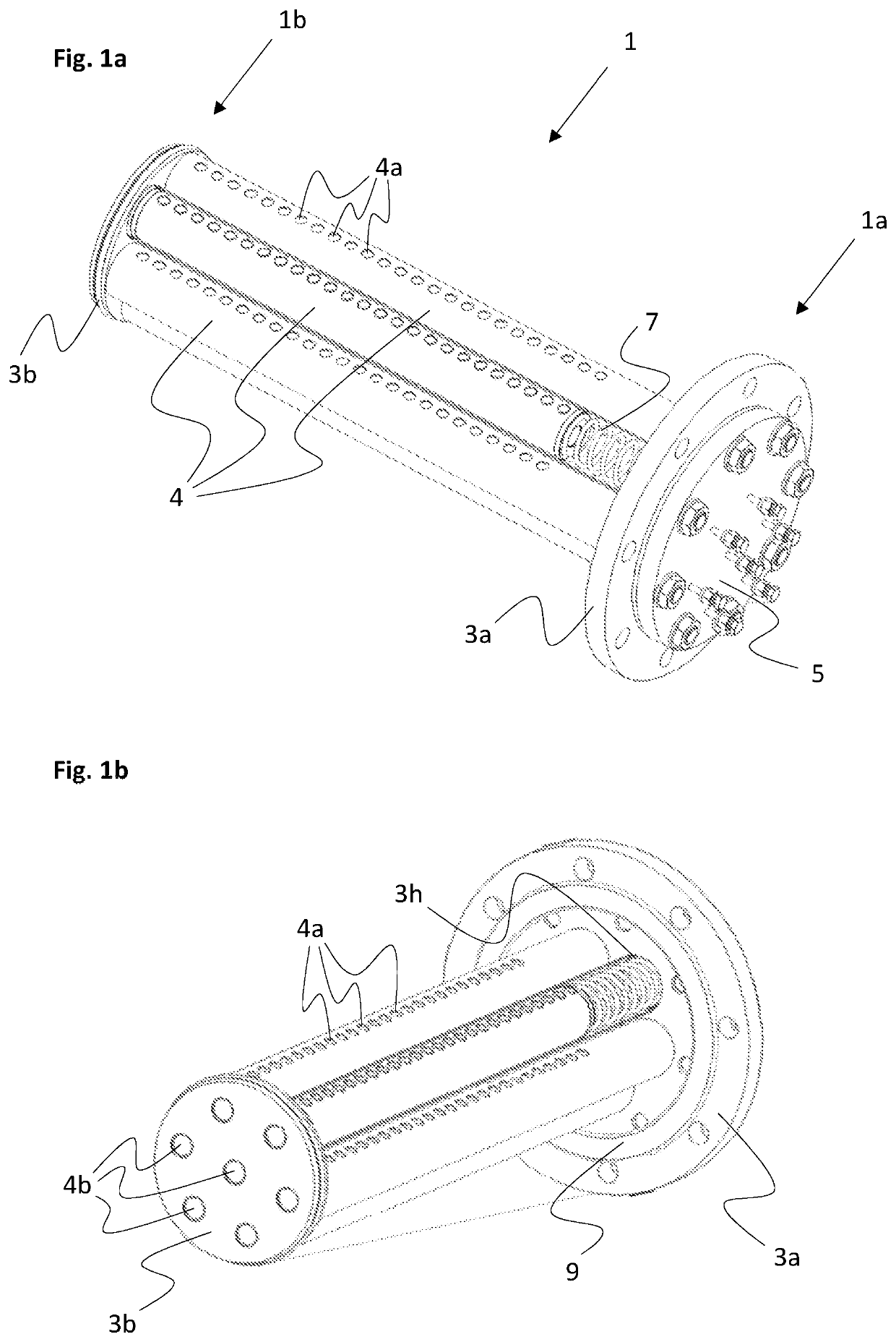
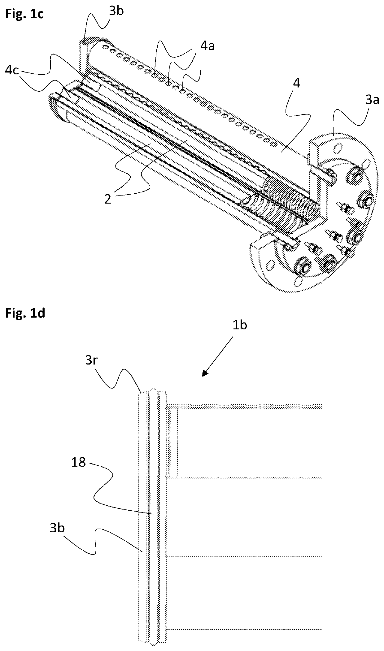
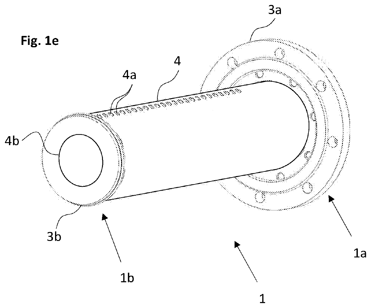
The present invention provides improved devices and methods for cleaning a plate heat exchanger. The invention includes a filter assembly that can be inserted directly into the inlet or outlet ports of the plate heat exchanger without additional pipe connections. The filter assembly includes one or more filter tubes with elongated filter elements for catching particles and contaminations. The filter tubes have inlet holes and a through-going outlet aperture in fluid communication with the interior of the filter tubes. The invention prevents particles and contaminations from returning to the plate heat exchanger when circulation of the working medium or cooling / heating fluid is stopped. When the filter assembly is removed, egress of filtered particles and contaminations is prevented. The plurality of inlet holes are arranged in a longitudinal direction of the filter tube and located in the same angular position with respect to the filter tube. The invention prevents ingress of fluid to be filtered to a specific angular position and egress of filtered particles and contaminations during removal of the filter assembly. The invention reduces the space required for carrying out a cleaning process of the working medium.

Problems solved by technology

During start-up and after long-term operation of the power generation module, the working medium can be contaminated by particles, e.g. due to wear and / or chemical reactions, which may damage the components in the power generation module.
However, such filter assemblies are time-consuming to connect and disconnect from the closed-loop cycle of the power conversion module and may not accumulate all unwanted particles.
Moreover, such a filter assembly requires additional space in the setting of the module, which is often not available.
Consequently, these filters also do not accumulate all unwanted particles in the working medium, while at the same time negatively affecting the flow rate through the plate heat exchanger.

Method used


Image

  • Filter assembly for plate heat exchangers and method of cleaning a working medium in a plate heat exchanger
  • Filter assembly for plate heat exchangers and method of cleaning a working medium in a plate heat exchanger
  • Filter assembly for plate heat exchangers and method of cleaning a working medium in a plate heat exchanger

Examples


Embodiment Construction

[0036]In the following, a detailed description of methods and devices for filtering a fluid, such as a working medium, in a plate heat exchanger according to the present invention is provided. In the drawing figures, like reference numerals designate identical or corresponding elements throughout the several figures. It will be appreciated that these figures are for illustration only and are not in any way restricting the scope of the invention.

[0037]In the context of the present invention, the terms ‘proximal’ and ‘distal’ used to describe features of the filter assembly shall be understood as referring to features that are located closest to and furthest away from the operator, respectively, as seen in an insertion direction of the filter assembly into an inlet or outlet port of a plate heat exchanger.

[0038]In the context of the present invention, the terms ‘upper’ and ‘lower’ used to describe features of the plate heat exchanger

[0039]In FIG. 1a, a filter assembly 1 according to o...


PUM

PropertyMeasurementUnit
Gravityaaaaaaaaaa
Levelaaaaaaaaaa

Abstract

A filter assembly for a plate heat exchanger comprising inlet and outlet ports for passage of a working medium and a cooling or heating fluid, respectively, wherein the filter assembly is dimensioned to fit into the inlet or outlet ports, wherein the filter assembly comprises a proximal flange and a distal flange and at least one filter tube attached at respective ends to the proximal flange and the distal flange, respectively, wherein the at least one filter tube is adapted to receive an elongated filter element and further comprises a plurality of inlet holes arranged on a circumferential surface thereof, and wherein the distal flange comprises at least one through-going outlet aperture in fluid communication with the interior of the at least one filter tube.

Description

TECHNICAL FIELD[0001]The present invention relates generally to plate heat exchangers and more specifically to a filter assembly for cleaning a working medium in a plate heat exchanger and a method of cleaning a working medium in a closed-loop cycle comprising a plate heat exchanger using a filter assembly.BACKGROUND ART[0002]There exist a number of systems and methods for converting low temperature heat or waste heat, e.g. from industrial processes or geothermal sources, into electricity by utilizing the phase change energy of a working medium produced in a thermodynamic closed-loop cycle such as a Rankine cycle, Organic Rankine Cycle (ORC), Kalina cycle or any other known thermodynamic closed loop power generating processes converting heat into power. For instance, WO 2012 / 128715 discloses such a heat conversion system including a power generation module. The power generation module comprises a turbine / generator, an evaporator / heat exchanger, a condenser and a main pump, and a wor...

Claims


Application Information

Patent Timeline
IPC IPC(8): B01D29/15B01D29/52B01D35/16B01D35/02F28D9/00F28F19/01
CPCB01D29/15B01D29/52B01D35/16B01D35/02F25B2339/0441F28F19/01B01D2201/0453B01D2201/0461F28D9/005F28F3/083F28F9/0273F28F9/028F28B1/02F28D2021/0063B01D2201/0415B01D29/13
Inventor BLOMQVIST, ERIKHILDING, KIMAHLBOM, ESKOMUNUKKA, KARI
Owner CLIMEON AB
Learn More