

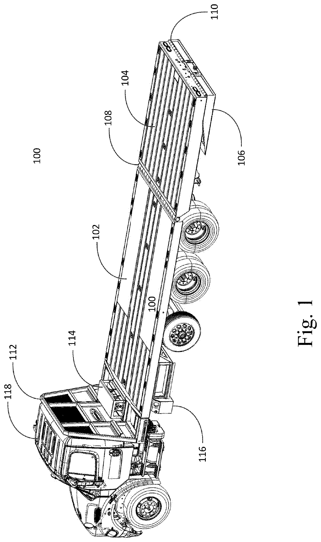
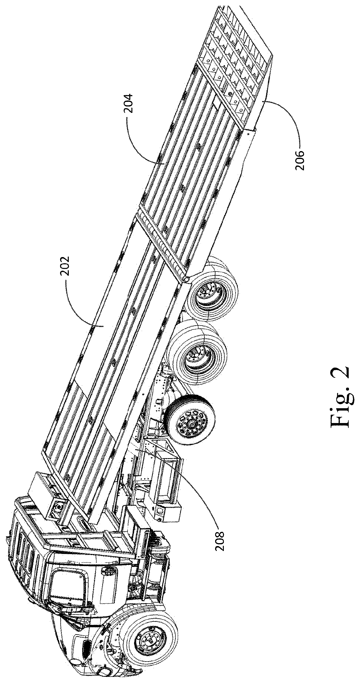
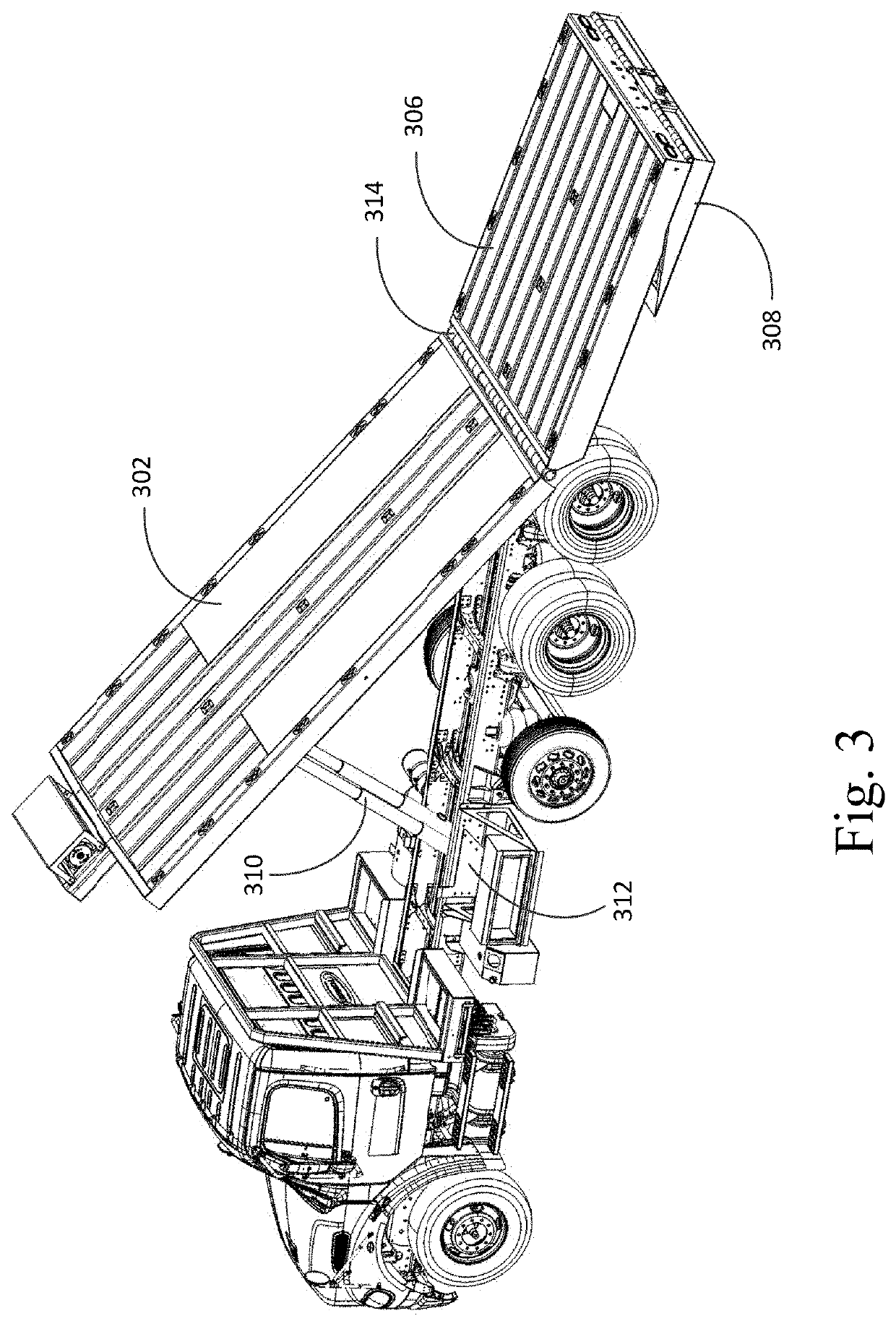
Truck load bed with hydraulic tilt/hydraulic tail that utilizes a unified hinge
a truck bed and hydraulic tilting technology, applied in the field of multi-part truck beds, can solve the problems of lack of flexibility of hydraulic tilting bed, failure to provide a single plane from the distal end of the bed section to the proximate end of the tail section, and problems with loading and unloading certain types of cargo, so as to eliminate the drawbacks
- Summary
- Abstract
- Description
- Claims
- Application Information
AI Technical Summary
Benefits of technology
Problems solved by technology
Method used
Image

Examples
Embodiment Construction
[0029]Subject matter will now be described more fully hereinafter with reference to the accompanying drawings, which form a part hereof, and which show, by way of illustration, exemplary embodiments in which the invention may be practiced. Subject matter may, however, be embodied in a variety of different forms and, therefore, covered or claimed subject matter is intended to be construed as not being limited to any example embodiments set forth herein; example embodiments are provided merely to be illustrative. It is to be understood that other embodiments may be utilized, and structural changes may be made without departing from the scope of the present invention. Likewise, a reasonably broad scope for claimed or covered subject matter is intended. Among other things, for example, subject matter may be embodied as methods, devices, components, or systems. The following detailed description is, therefore, not intended to be taken in a limiting sense.
[0030]Throughout the specificatio...
PUM
 Abstract
Description
Claims
Application Information