Operating device

Pending Publication Date: 2021-07-22
ALPINE ELECTRONICS INC
View PDF8 Cites 0 Cited by
  • Summary
  • Abstract
  • Description
  • Claims
  • Application Information

AI Technical Summary

Benefits of technology

[0022]In the operating device of the present disclosure, relative movement of the operating unit with respect to the supporting member is regulated by the lock mechanism unit. When input of an operator is detected by the operation detector, locking of the lock mechanism unit is released by the controller, and after the locking

Problems solved by technology

However, the support stiffness level of the supporting body cannot be switched when an operator is operating and when an operator is not operating.
Thus, when operating, an operator

Method used


Image

  • Operating device
  • Operating device
  • Operating device

Examples


first embodiment

[0057]FIG. 8 is a flowchart illustrating the display processing on an operation screen according to the

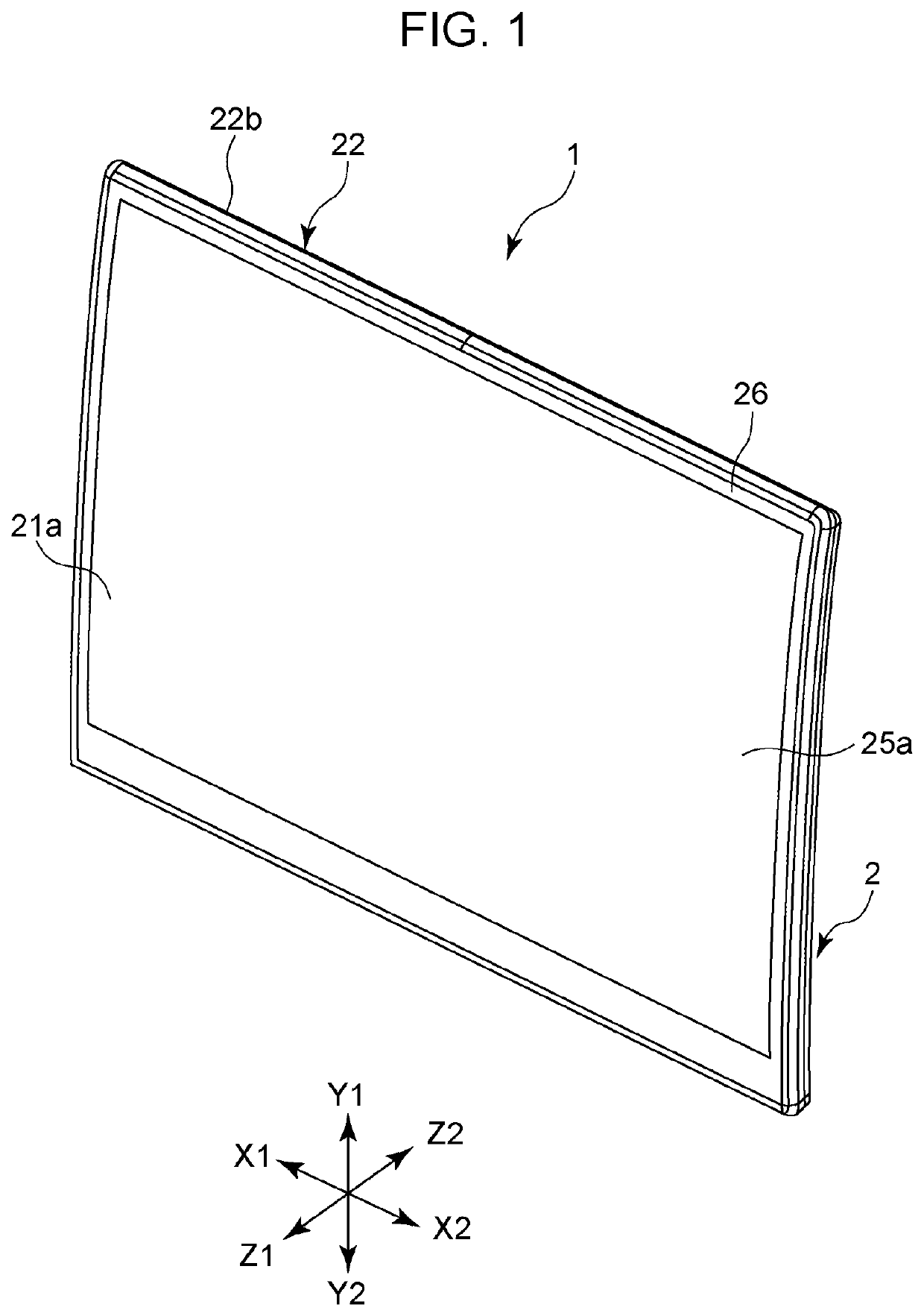
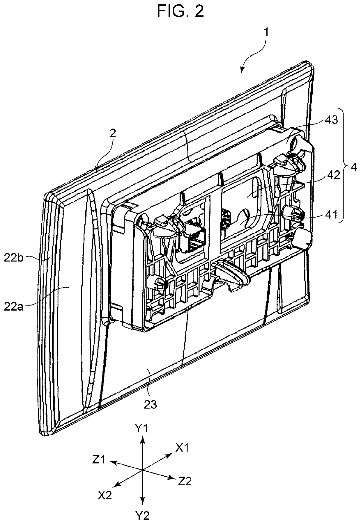
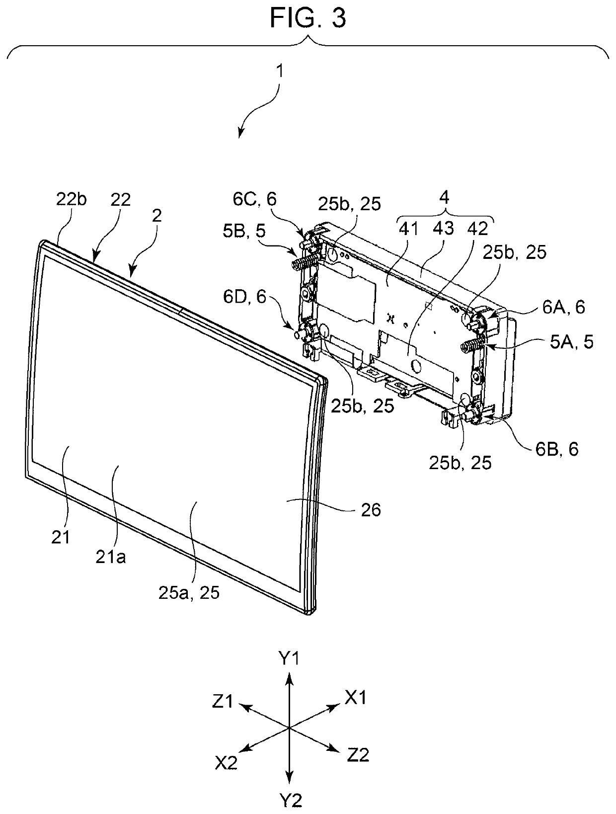
[0058]In the operating device 1 used as an in-vehicle display device, it is determined whether or not a finger of an operator has come into contact with any position of the surface panel 26 based on the detection signal from the first detection member 25a (step S1). When the first detection member 25a detects contact of a finger of an operator with the surface panel 26, the controller 7 issues a command to release the locking to the lock mechanism unit 6. When a command to release the locking is issued, the current flowing through the electrical magnet provided in the magnetic relay (not illustrated) fixed onto the main substrate 41 is cut off. Thus, no magnetic force is generated between the ring body and the seating face section of the lock body provided in each of the first lock mechanism 6A, the second lock mechanism 6B, the third lock mechanism 6C and the fourth lock mechanism...

second embodiment

[0065]The proximity detection member 25c in the second embodiment is fixed to the front surface which is toward the forward direction (the Z1 direction) of the display device 21. The proximity detection member 25c is a proximity sensor that detects an approach of a hand to the display screen 21a of the display device 21 by a photosensor including a light emitting element and a light receiving element. The contact detection member 25d is an electrostatic capacitance sensor provided in the rear surface of the surface panel 26, or a resistance sensor provided in the front surface of the surface panel 26. The coordinate position where a finger is in contact with the surface panel 26 in the display screen 21a is detected by the contact detection member 25d. Pressing the operating unit 2 in the rearward direction (the Z2 direction) causes the detector face 22c of the exterior case 22 to approach the pressure detection member 25e of the main substrate 41, and when the detector face 22c is ...


PUM


Abstract

An operating device includes a lock mechanism unit that regulates relative movement of an operating unit with respect to a supporting member, and a controller that releases locking of the lock mechanism unit when input of an operator is detected by an operation detector. When contact of a finger with a surface panel is detected by a first detection member, locking of the operating unit by the lock mechanism unit is released. In addition, when a pressing operation to the operating unit is detected by a second detection member, control is performed so that a response force providing mechanism operates.

Description

RELATED APPLICATION[0001]The present application claims priority to Japanese Patent Application Number 2020-006438, filed Jan. 18, 2020, the entirety of which is hereby incorporated by reference.BACKGROUND1. Field of the Invention[0002]The present invention relates to an operating device equipped with an operating unit including an operation detector, and a response force providing mechanism that provides a response force to the operating unit.2. Description of the Related Art[0003]In recent years, operating devices are required to provide a favorable response feeling to an operator when operating the device.[0004]In the operating device described in Japanese Patent No. 6304397, a supporting body and a vibrating element are bonded to the surface of a top panel on the Z-axis negative direction side, and the top panel is fixed to a housing by the supporting body.[0005]The supporting body is designed to be able to switch between two levels of the support stiffness across the end on the...

Claims


Application Information

Patent Timeline
IPC IPC(8): E05B47/00E05B65/00
CPCE05B47/0002E05B65/00B60K35/00E05Y2900/606E05Y2400/86B60K37/06B60K2370/1438B60K2370/158B60K2370/199B60K2370/60B60K2370/152B60K2370/143
Inventor OTSUKA, TOMOKI
Owner ALPINE ELECTRONICS INC
Why Eureka
Try Eureka