Arrangement for generating an output voltage

Inactive Publication Date: 2014-01-30
ZENT MIKROELEKTRONIK DRESDEN
View PDF4 Cites 2 Cited by
  • Summary
  • Abstract
  • Description
  • Claims
  • Application Information

AI Technical Summary

Benefits of technology

The patent describes a method to improve compensation for temporary changes in control voltage. It involves providing a control signal that helps to correct the control deviations before the control loop can do so. The control signal is ended at a good time, and then the control loop picks up again to monitor the control voltage. The technical effect is to enhance the stability and accuracy of control voltage.

Problems solved by technology

In the case of switching converters, this is particularly problematic since they are usually operated in various operating modes for optimizing their efficiency.
The mentioned control deviations have a particularly negative effect in the case of switching converters since, for example on transition from a low load to a high load, the speed at which the connected coil can follow the load current changes is limited by its inductance and the speed of the implemented control loop.
It should be noted that the implemented control loops generally need to meet stability criteria which make these control loops slow and therefore the transient deviation unnecessarily great.

Method used


Image

  • Arrangement for generating an output voltage
  • Arrangement for generating an output voltage
  • Arrangement for generating an output voltage

Examples


Embodiment Construction

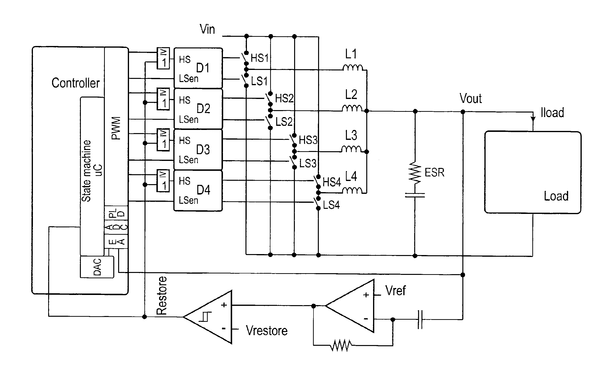
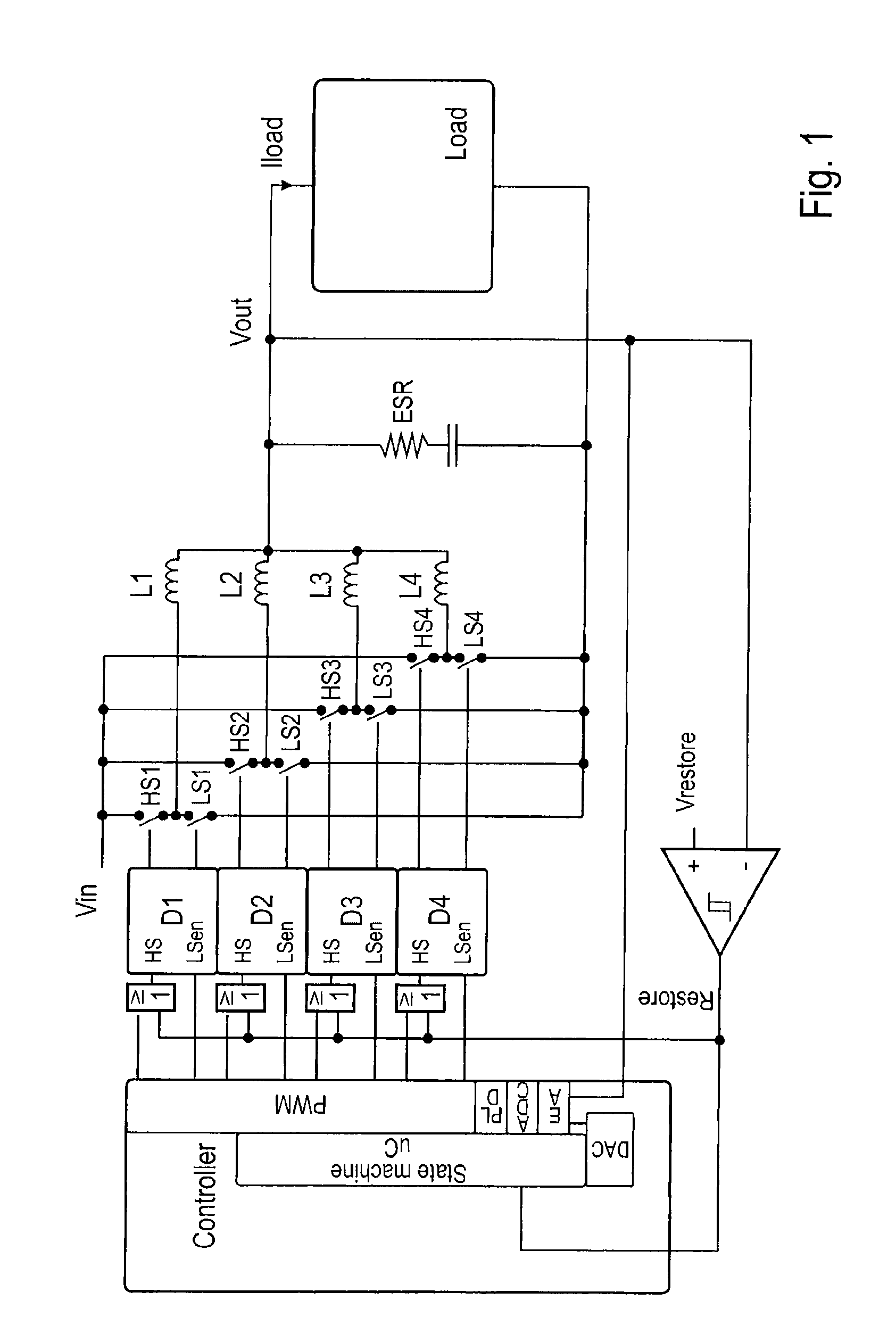
[0013]The principle is illustrated using the example of a 4-phase digital DC / DC controller. It is not restricted to this embodiment. The illustrated method can also be used for single-phase digital controllers or for analog multi-phase and single-phase controllers.

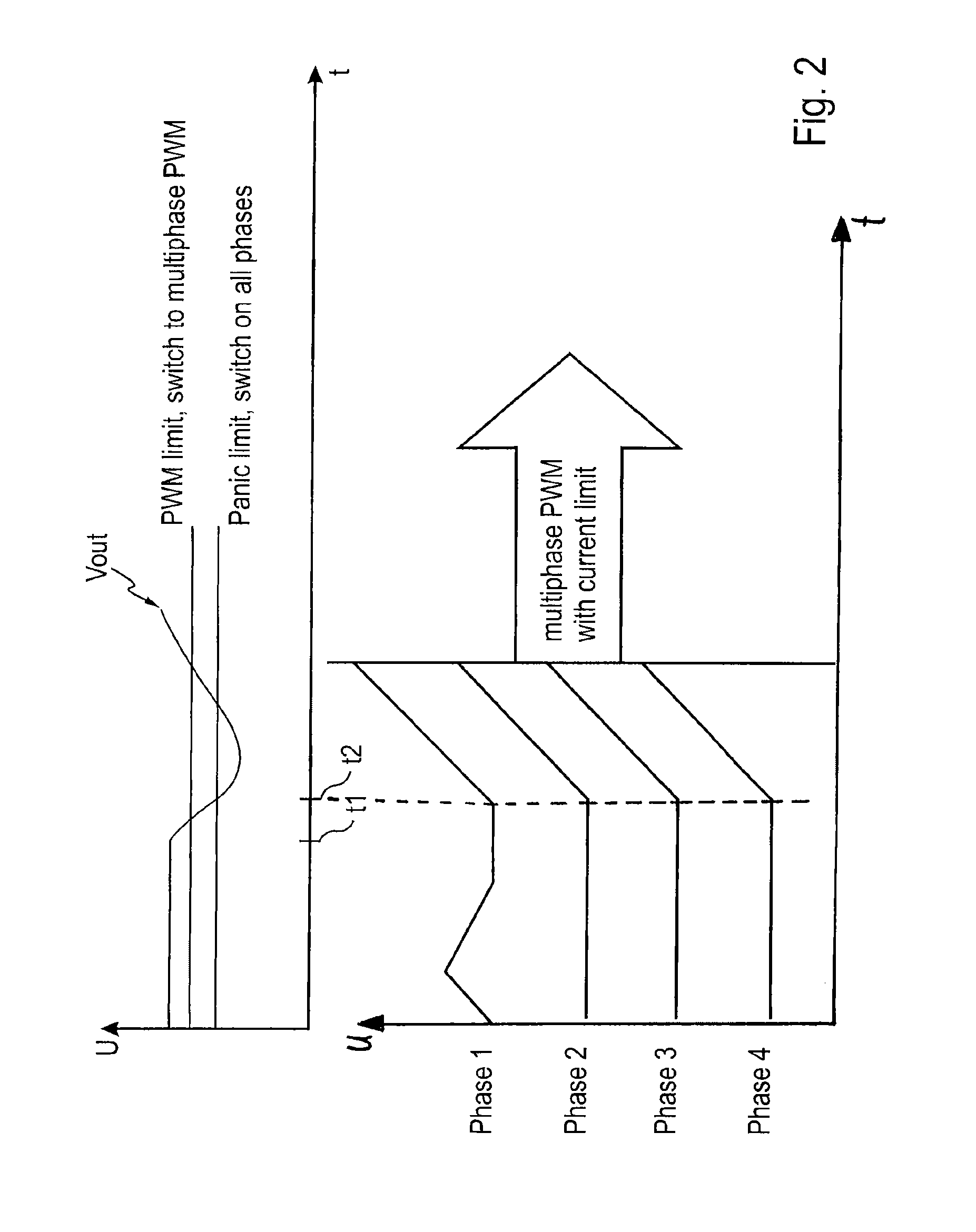
[0014]The mode of operation is illustrated with reference to a block circuit diagram in FIG. 1 and to a graph illustrating the associated voltage / time profiles in FIG. 2. The DC-to-DC converter illustrated in FIG. 1 comprises, by way of example, a controller for controlling the arrangement itself, logic gates, gate drivers D1 to D4, the high-side switches HS1, HS2, HS3 and HS4, the low-side switches LS1, LS2, LS3 and LS4 and the inductances L1 to L4 at the output of the converter, at which the output voltage (control voltage) Vout is provided. A load “Load” is connected at the output. The current Iload flows through this load. In order to regulate the value of the voltage Vout, a comparator is interposed between the output...


PUM


Abstract

When generating a voltage Vout of a DC-to-DC converter for a load which is connected to the converter, it is necessary to monitor the quality of the voltage, in particular its amplitude. For this, provision is made for a comparator to be arranged between the output of the DC-to-DC converter and a control input of the control unit, with a first input of the comparator being connected to the output of the DC-to-DC converter (Vout), the second input of the comparator being connected to a reference voltage (Vrestore) and the output of the comparator being connected to the control input of the control unit of the DC-to-DC converter, for controlling the voltage Vout.

Description

CROSS REFERENCE TO RELATED APPLICATIONS[0001]This application claims priority of provisional application Ser. No. 61 / 668,691 filed on Jul. 6, 2012, the entire contents of which is hereby incorporated by reference herein.BACKGROUND OF THE INVENTION[0002]Voltage regulators can generally only compensate for rapid transient load changes to a limited extent, i.e. the output voltage thereof experiences deviations from the control voltage, so-called transient deviations, depending on the extent of the load change. The implemented control loops compensate for these control deviations generally over time. In the case of switching converters, this is particularly problematic since they are usually operated in various operating modes for optimizing their efficiency. Thus, a distinction is generally drawn between the discontinuous mode (DCM) and the continuous mode (CCM). In this case, the transition between the modes can take place continuously or in a manner triggered by thresholds by virtue ...

Claims


Application Information

Patent Timeline
IPC IPC(8): H02M3/158
CPCH02M3/158H02M3/1584Y02B70/10H02M1/0048H02M3/1566
Inventor SCHMITZ, RICHARD MARIAMARSCHALKOWSKI, ERICLAM, ED
Owner ZENT MIKROELEKTRONIK DRESDEN
Why Eureka
Try Eureka