Hydraulic clutch release device

A release device and clutch technology, which is applied in the field of clutches, can solve the problems of insufficient stability, cost, and inaccurate elastic compression force, and achieve better timing and effect, and simple structure

Active Publication Date: 2018-05-11
陈德三
View PDF8 Cites 0 Cited by
  • Summary
  • Abstract
  • Description
  • Claims
  • Application Information

AI Technical Summary

Problems solved by technology

[0003] As far as the spring is concerned, during the elastic expansion and contraction process, it is generally carried out between the pressing end ring and the pressure end ring at the two ends, and is sleeved on the outer edge of a frame sleeve provided by a bearing seat. The spring expands and contracts in the axial direction, but because the pressing end ring at one end of the pressing spring is often not completely straight during the movement process, it is inevitable to cause sliding or twisting during the spring compression process, so that the elastic compression force cannot be accurately applied
[0004] Although there is Japanese Patent No. 2002-340027 case, which presents a structure that can limit the sliding of the spring, it is mainly provided with a spring between the pressing end rings at the two ends and the axial inner sides of the pressure receiving end rings. The so-called "engaging claws" that can resist each other's rotation, use the engaging claws of the pressing end ring and the pressure-bearing end ring to restrict rotation (prevent twisting), so that the pressing end ring responsible for pressing the spring can maintain a considerable linear motion to ensure The compression spring can be accurate, but the technical means of the Japanese prior document is to provide a so-called "engagement claw" that can resist each other to rotate between the pressing end ring and the axial inner side of the pressure end ring at the two ends, so the assembly It is cost-intensive, and the pressing end ring responsible for pressing the spring is engaged with the pressing end ring at the other end, and the stability is not enough

Method used


Image

  • Hydraulic clutch release device
  • Hydraulic clutch release device
  • Hydraulic clutch release device

Examples


Embodiment Construction

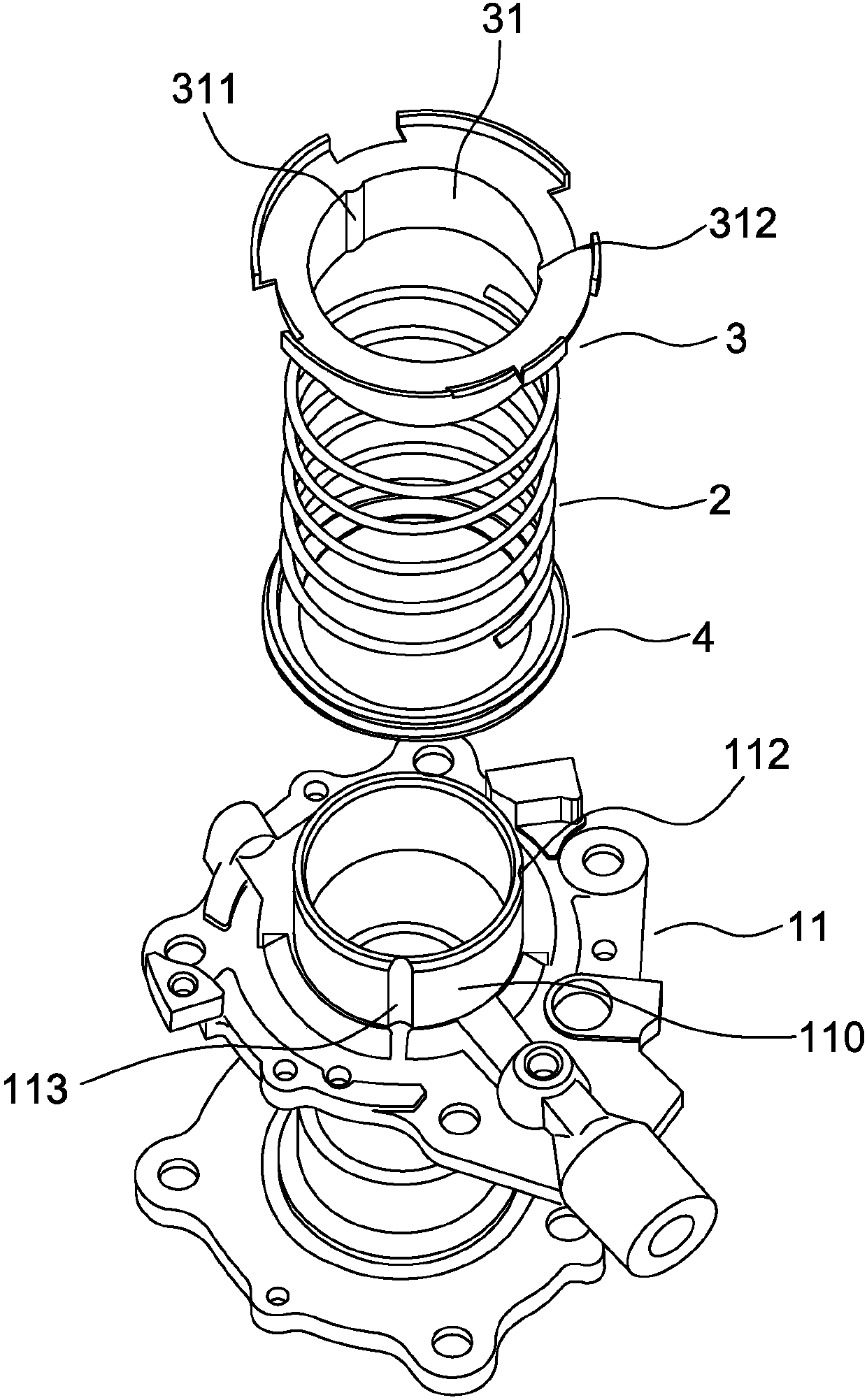
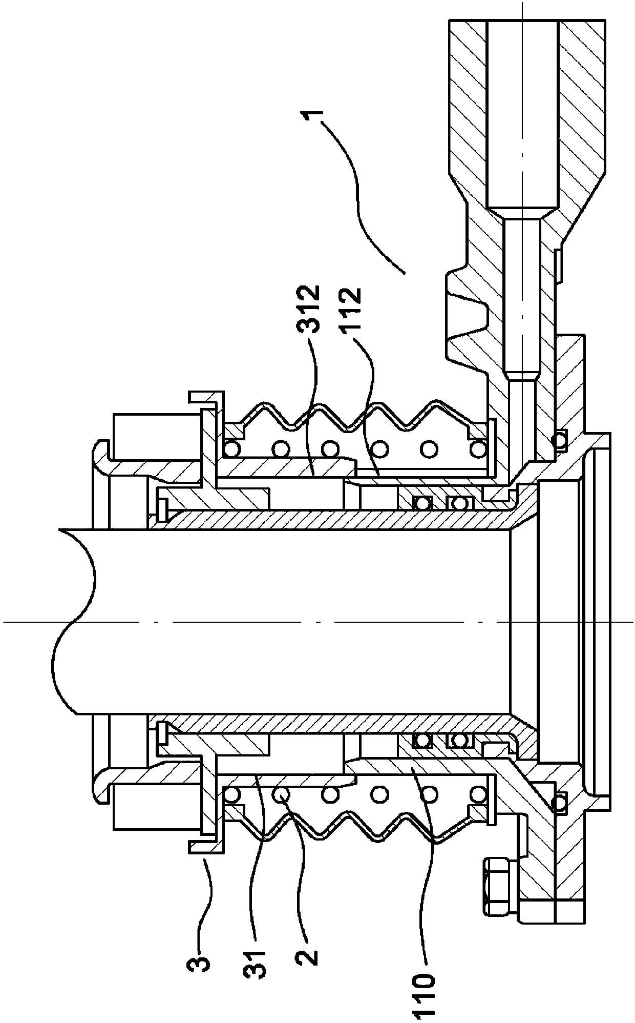
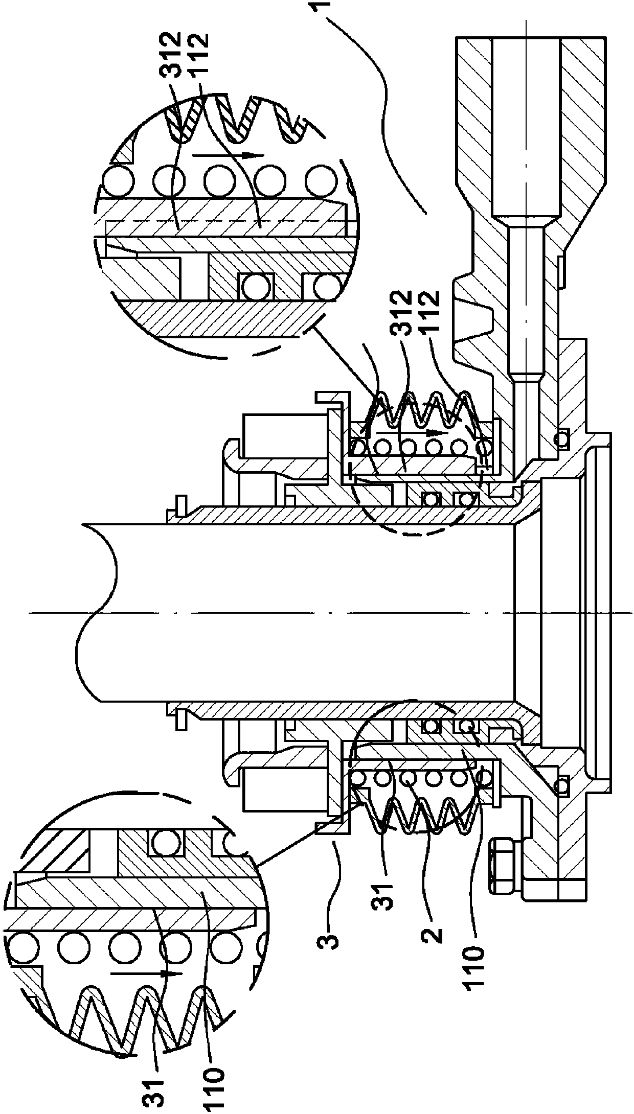
[0028] see figure 1 As shown, the present invention relates to a hydraulic clutch release device, which is arranged on a hydraulic clutch main body 1 and cooperates with figure 2 As shown, the hydraulic clutch release device of the present invention includes a spring 2, which is sheathed on the outer edge of a frame sleeve 110 of a bearing seat 11 provided by the hydraulic clutch main body 1, and the spring 2 includes at least one end It is arranged against a pressing end ring 3, and the other end of the spring 2 is against a pressure-bearing end ring 4 opposite to the pressing end ring 3, or against other fixed objects.

[0029] Wherein the pressing end ring 3 extends a ring plate 31 from the end toward the bearing seat 11, the ring plate 31 is sleeved on the outer edge of the frame sleeve 110, and the inner edge of the ring plate 31 protrudes from the first rib 311, the The outer edge of the frame cover 110 is provided with a first groove 112 that allows the first rib 311 ...


PUM


Abstract

The invention relates to a hydraulic clutch release device and mainly provides a simple slide-limiting structure capable of enabling a clutch to be more stable in a compression spring path. Accordingto the structure, by arranging a simple first convex rib and forming a first groove channel allowing the first convex rib to be stored in the outer edge of a frame sleeve, the structure can be used for limiting displacement, sliding or deviation of a pressing end ring and is simple. The first groove channel is formed in the frame sleeve, that is, the pressing end ring is stored in the limited structure during initial pressing, and thus the time sequence and the effect are better.

Description

technical field [0001] This invention relates to a clutch for operating an automobile engine and a transmission, and more particularly to a clutch release device. Background technique [0002] The clutch is mainly used as a rotating machine, especially a vehicle. When the pedal or pressing device is stepped on during the speed change process, the spring is pressed, and the pressed part is separated from the friction plate, so that the friction plate and the flywheel are separated from the connection and linkage (that is, the general The so-called neutral state), even if the engine is running at this time, the power will not be transmitted to the gearbox, which is beneficial to the operator (or vehicle driver) to shift gears. On the contrary, when the pedal or the suppressing device are relaxed in the speed change process, the spring is pressed from the spring, and the connection and interlocking are restored between the friction plate and the flywheel (i.e., the generally ca...

Claims


Application Information

Patent Timeline
Patent Type & Authority Applications(China)
IPC IPC(8): F16D25/12F16D25/00
CPCF16D25/00F16D25/12
Inventor 陈德三
Owner 陈德三
Why Eureka
Try Eureka