
Gauge wheel cover crop crimper

a crop crimper and wheel cover technology, applied in the field of earth-engaging agricultural implements, can solve problems such as affecting seed depth, and achieve the effect of eliminating separate crimping and seeding operations

Inactive Publication Date: 2021-07-29
HEINEN RODNEY R
View PDF0 Cites 0 Cited by
  • Summary
  • Abstract
  • Description
  • Claims
  • Application Information

AI Technical Summary

Benefits of technology

The invention provides agricultural implements that have a soil-engaging device with crimper wheels that can crimp surface crops as the implement moves through a field. These implements can be planters, fertilizers, drills, scarifiers, and any other type of soil-conditioning equipment. The crimper wheels on these implements serve two purposes, they crimp the crops and also act as (often large) gauge wheels. This eliminates the need for separate crimping and seeding operations. The crimper wheels are also designed with elongated bar elements that move crop and trash outward to prevent clogging, and a non-orthogonal angle between the rims and bar elements provides proper crimping without excessive bouncing that could affect seed depth. Overall, the invention provides a more efficient and effective solution for soil-engaging and crop-crimping in agricultural production.

Problems solved by technology

This is to be contrasted with perpendicularly oriented bars which could create excessive “bouncing” which may affect seed depth.

Method used


Image

  • Gauge wheel cover crop crimper
  • Gauge wheel cover crop crimper
  • Gauge wheel cover crop crimper

Examples


Embodiment Construction

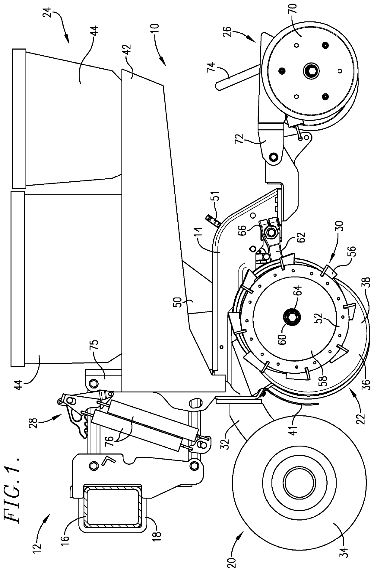
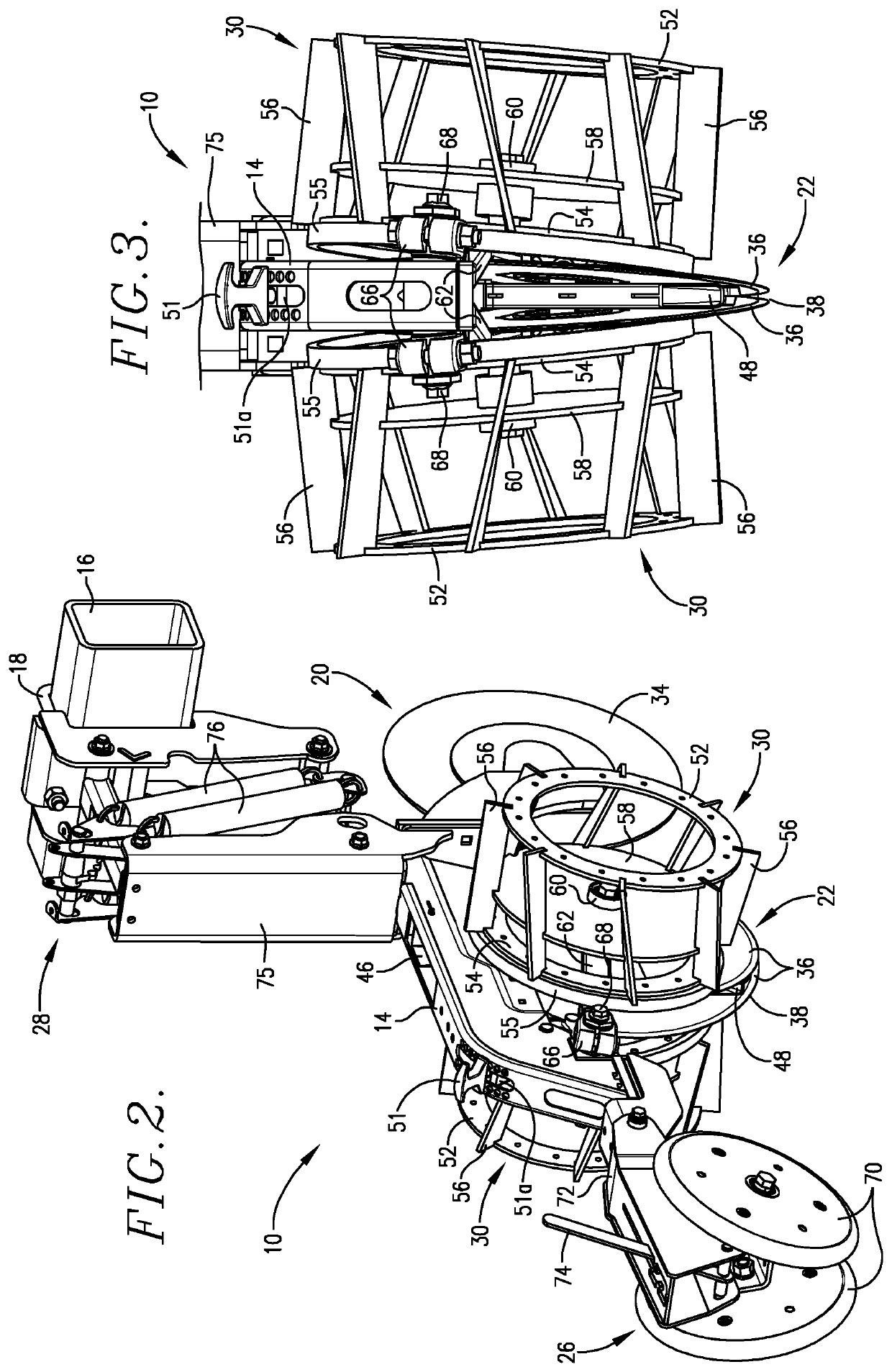
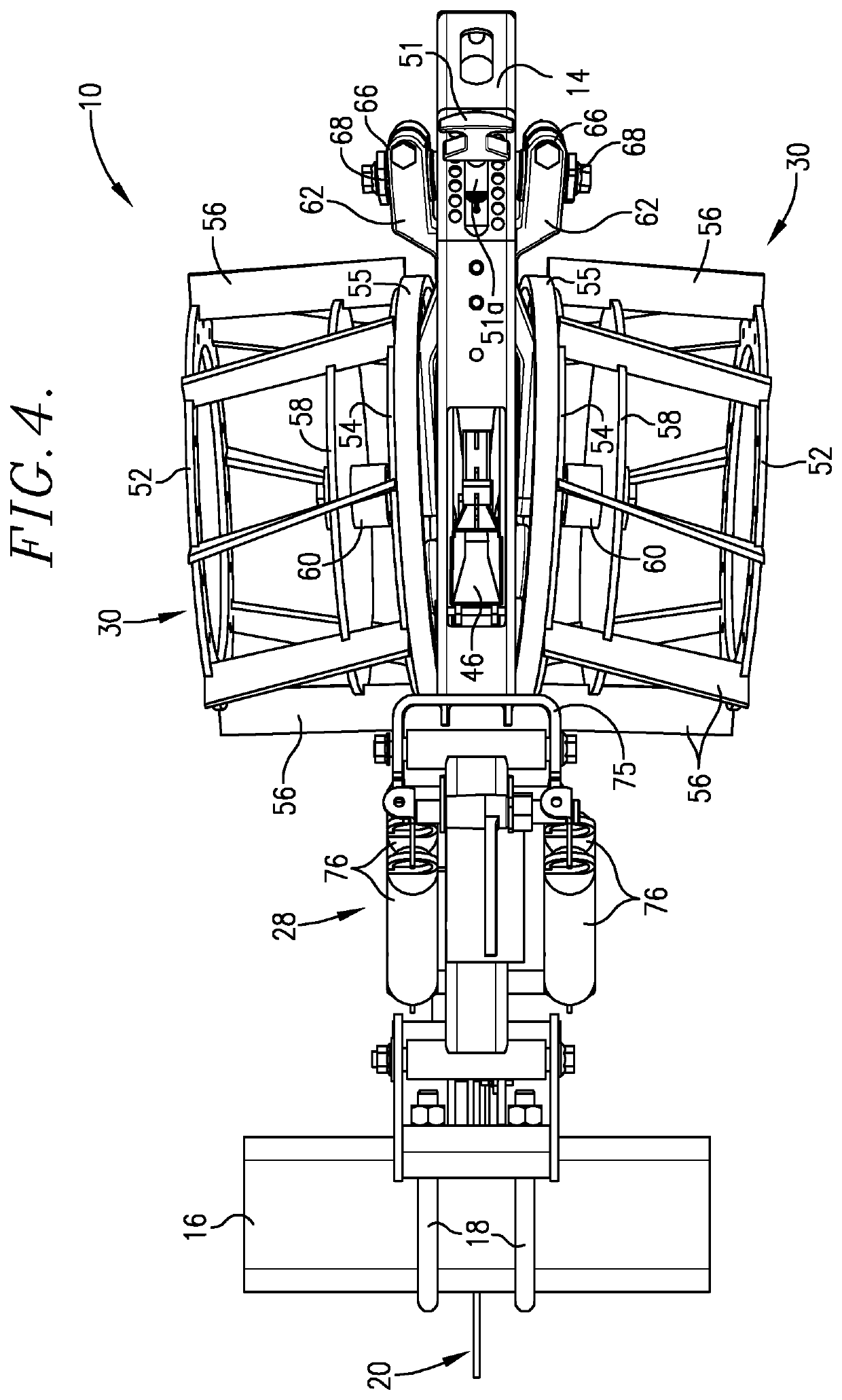
[0018]Turning now to the drawings, and particularly FIG. 1, a row unit 10 forming a part of a planter implement 12 is illustrated in FIG. 1. Generally, a plurality of such row units would be used in an overall planter, in order to plant successive rows of seed in a field. Broadly, the row unit 10 includes a fore-and-aft extending unit body 14 which supports the various assemblies of the unit and is attached to a tool bar 16 by means of U-bolts 18 or similar expedients. In more detail, the unit body 14 is equipped with a forward coulter assembly 20, an intermediate furrowing assembly 22, a seed fertilizer assembly 24, a rearmost furrow-closing assembly 26, and a parallel arm assembly 28. The assembly 22 includes a pair of specialized crimper wheels 30 on opposite sides thereof, which are important for purposes to be explained.

[0019]The coulter assembly 20 is itself conventional and includes a forwardly extending arm 32, which rotatably supports an earth-penetrating coulter blade 34 s...


PUM


Abstract

A planter implement (12) includes one or more row units (10) equipped with a furrowing assembly (22), a seed / fertilizer assembly (24), and a furrow-closing assembly (26). The unit (10) is equipped with a pair of right- and left-hand crimper wheels (30) respectively mounted on opposite sides of the furrowing assembly (22). Each crimper wheel (30) has a pair of support rims (52, 54) with a series of elongated bar elements (56) extending between and secured to the rims (52, 54). The bar elements (56) extend beyond the outer periphery of the rims (52, 54) in order to crimp surface crops as the row units (10) pass over a field; the bar elements (56) are oriented to direct material outwardly from each wheel (30) in order to prevent clogging thereof. The crimper wheels (30) are adjustably mounted on the row units (10) and serve as gauge wheels for the units (10).

Description

BACKGROUND OF THE INVENTIONField of the Invention[0001]The present invention is concerned with improved earth-engaging agricultural implements equipped with a pair of laterally spaced apart, rotatable crimper wheels operable to crimp surface crops as the implement traverses a field. More particularly, the invention is concerned with such implements, the crimper wheels themselves, and corresponding methods; the crimper wheels preferably comprise substantially circular rims with a plurality of elongated, circumferentially spaced apart bar elements secured to said rims and extending outwardly beyond the outer margins of the rims. The crimper wheels also serve as gauge wheels for the implement.Description of the Prior Art[0002]Many large-scale farming operations rely heavily on tillage for weed control. Tillage breaks up the soil to kill weeds and prepare for planting. However, intense tillage can compact the soil, cause erosion, and deplete soil nutrients; moreover, tillage is fuel- an...

Claims


Application Information

Patent Timeline
IPC IPC(8): A01B49/04A01C7/00
CPCA01B49/04A01C7/006A01C5/068Y02P60/20
Inventor HEINEN, RODNEY R.
Owner HEINEN RODNEY R
Learn More