
Flexible cooling system with thermal energy storage

a technology of flexible cooling and thermal energy storage, applied in the direction of domestic cooling equipment, indirect heat exchangers, lighting and heating equipment, etc., can solve the problem of system not providing rapid cooling features

Active Publication Date: 2021-07-29
ROCKY RES
View PDF5 Cites 2 Cited by
  • Summary
  • Abstract
  • Description
  • Claims
  • Application Information

AI Technical Summary

Benefits of technology

The invention is a thermal management system for a high energy laser that includes a vapor compression system, a thermal energy storage system, and a complex compound burst cooling system. The system can cool the laser and its ancillary equipment during operation. The method involves detecting laser activation, initiating cooling, and using the vapor compression system and complex compound burst cooling system to absorb and dissipate the heat. The system can also have a thermal transfer liquid circulating through a cooling loop controlled by pumps and a vector control system. The invention provides improved cooling efficiency and reliability compared to existing systems.

Problems solved by technology

However, these systems do not provide rapid cooling features since these systems may take up to a minute or in some cases more to reach full capacity and usually several minutes or longer to provide cooling to the target heat load.

Method used


Image

  • Flexible cooling system with thermal energy storage
  • Flexible cooling system with thermal energy storage
  • Flexible cooling system with thermal energy storage

Examples


Embodiment Construction

,” one will understand how the features of the embodiments described herein provide advantages over existing systems, devices and methods.

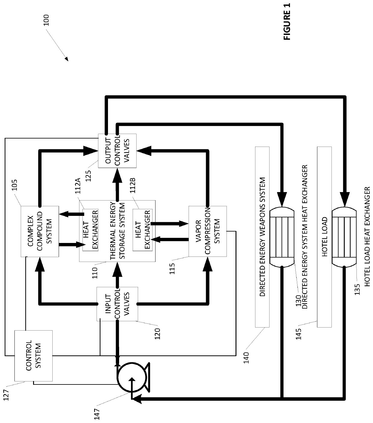
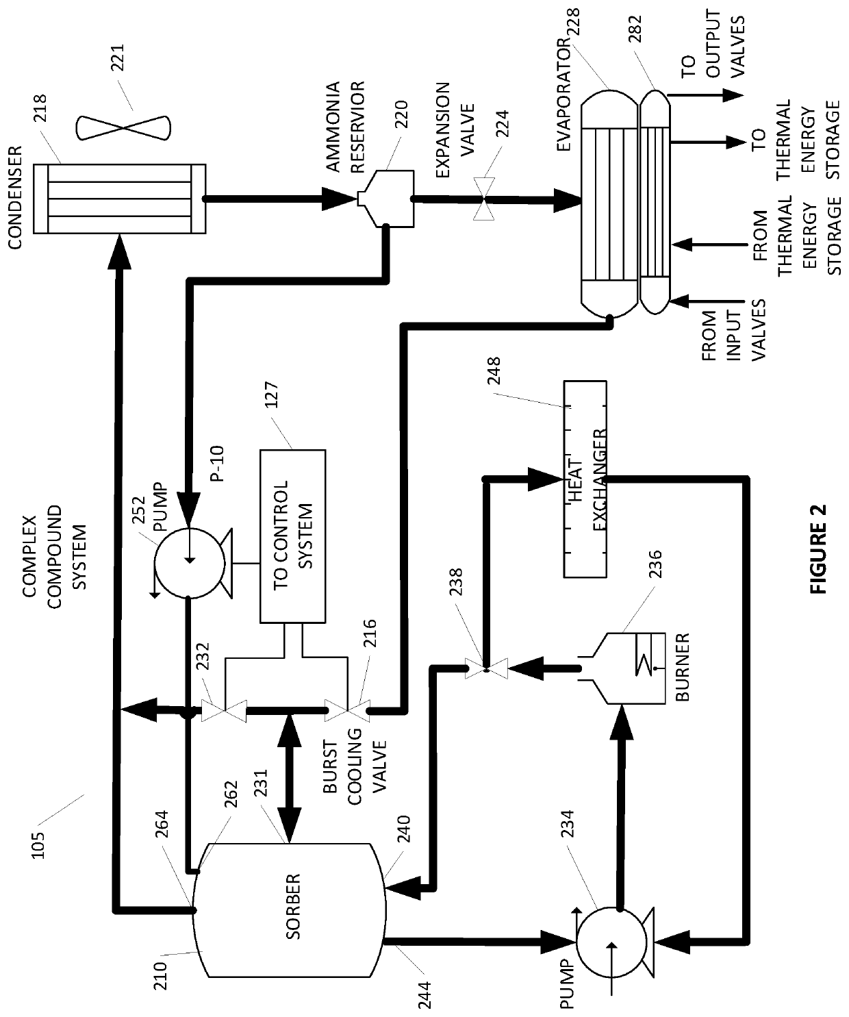
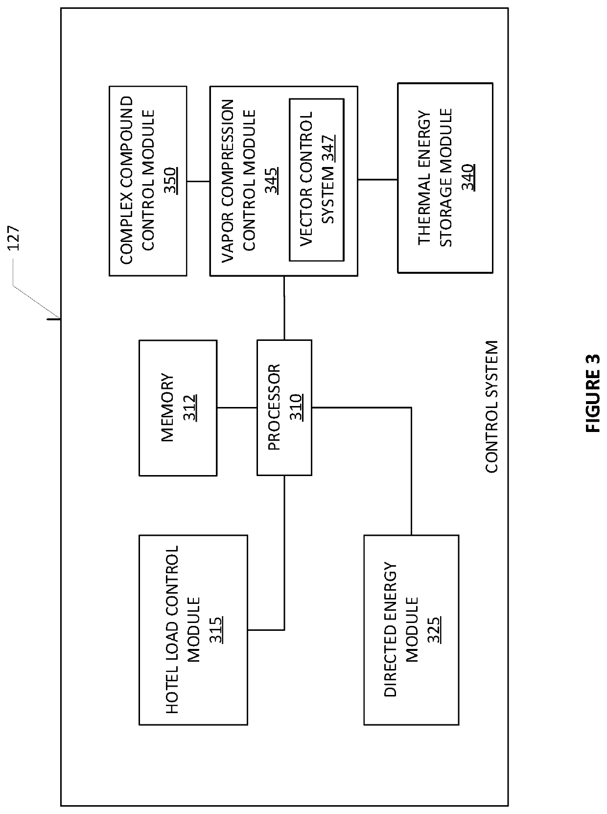
[0006]One embodiment of the invention is a thermal management system for a high energy laser. This embodiment may include: a vapor compression system; a thermal energy storage system comprising a phase change material; and a complex compound burst cooling thermal energy storage system, wherein the thermal energy system and complex compound burst cooling system are in thermal communication with the high energy laser, and the vapor compression system is configured to cool ancillary equipment connected to the high energy laser. In one embodiment, the vapor compression system is configured to cool the thermal energy storage system. In another one embodiment the vapor compression system is also configured to supplement laser cooling during periods where the high energy laser is active.

[0007]Another embodiment is a method of cooling a high energy laser....


PUM


Abstract

Disclosed are systems and methods of flexibly cooling thermal loads by providing a complex compound system for burst mode cooling, a vapor compression system for ancillary cooling, and a thermal storage system for helping efficiently maintain and cool a thermal load such as a directed energy weapon system.

Description

BACKGROUNDField of the Invention[0001]This disclosure relates generally to a flexible refrigeration system that provides rapid cooling features in conjunction with a thermal energy storage system. In particular, the system may include a complex compound cooling system to cool rapid bursts of heat, a thermal energy storage system, and a conventional vapor compression system.Description of the Related Art[0002]Adsorption / desorption or also referred to as absorption / desorption reactions between polar gases and certain metal salts yield complex compounds which are the basis for efficient refrigeration, thermal storage, heat pump systems and power systems having high energy density. However, energy density, a measure of the quantity of polar gas adsorbed on the salt, which translates into the amount of work or energy which can be stored in a given amount of the complex compound, is only one parameter to be considered in designing commercially attractive systems. Complex compound systems ...

Claims


Application Information

Patent Timeline
IPC IPC(8): F28D20/02F25B1/00F41H13/00F28D20/00
CPCF28D20/028F25B1/00F25B41/04F28D20/0056F41H13/005F25B25/005F25B17/08F25B2400/24F25B49/046F25B2700/2104F25D17/02F25B25/02Y02E60/14F25B41/20F25B2400/053F28D2020/0047F28D2020/0078
Inventor ROCKENFELLER, UWEKHALILI, KAVEH
Owner ROCKY RES
Learn More