
Storing Thermal Energy and Generating Electricity

a technology of thermal energy and thermal energy, applied in steam engine plants, machines/engines, propulsion parts, etc., can solve the problems of lack of technical elegance of electrothermal energy storage, limited to few suitable geographic locations and large plant sizes, and low cost per kw (“conversion cost or power cost”), so as to avoid the doubling of essential components

Inactive Publication Date: 2008-01-31
ABB RES LTD
View PDF9 Cites 78 Cited by
  • Summary
  • Abstract
  • Description
  • Claims
  • Application Information

AI Technical Summary

Benefits of technology

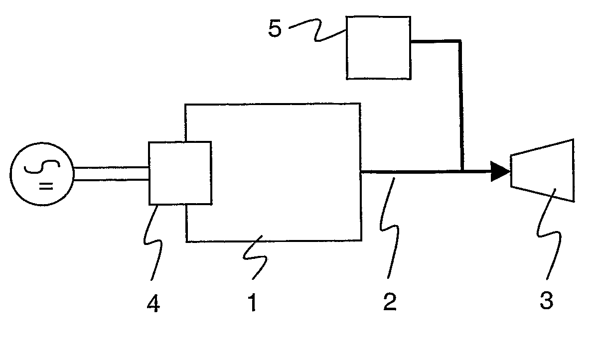
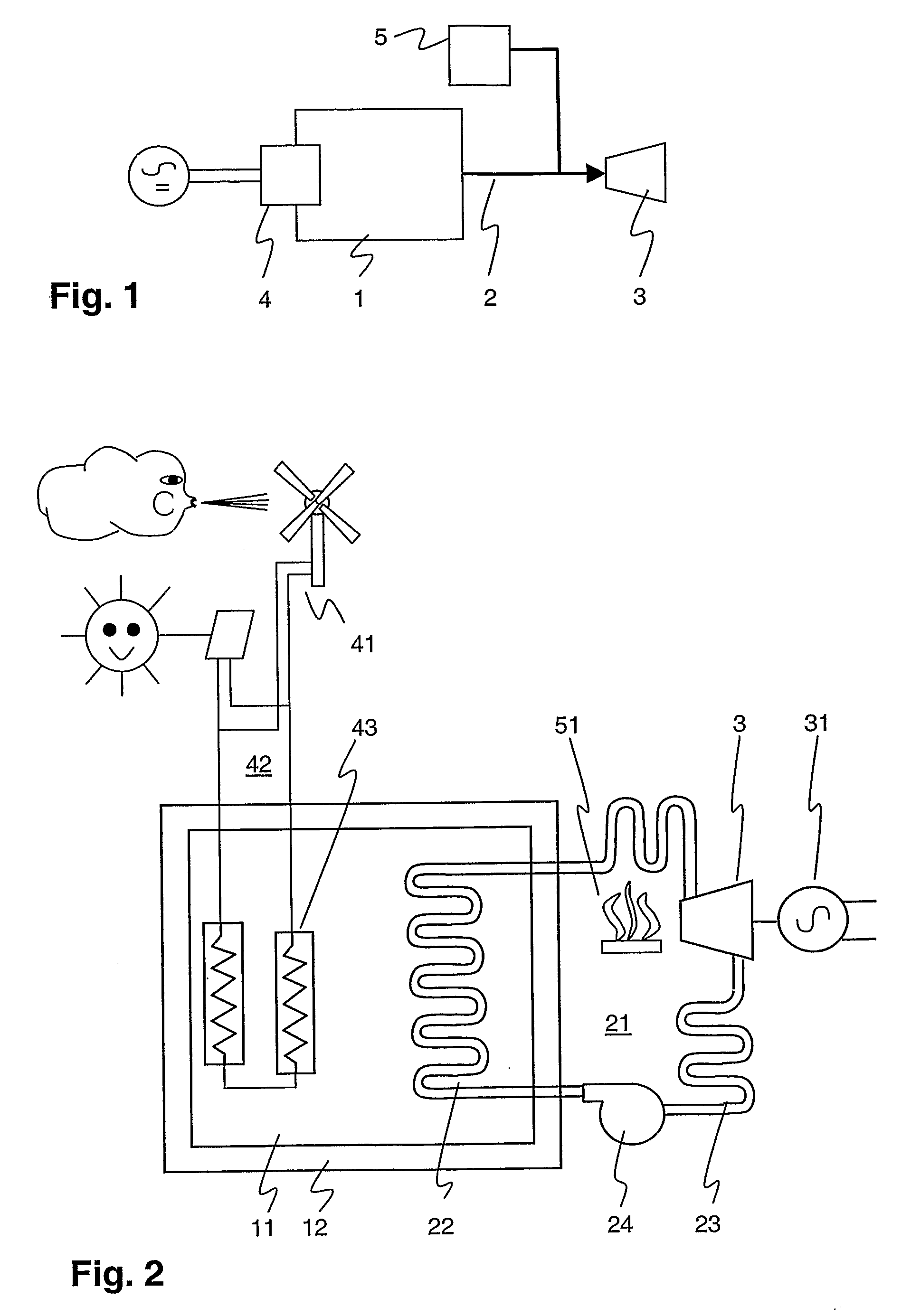
[0011]According to the invention, a source of electrical power supplies electricity to a first heat generating means which converts the electricity into heat to be stored in a heat storage device. The heat is occasionally retrieved, via first heat transfer means, from the device and provided to a thermodynamic machine for generating electricity such as a thermal machine in expansion mode, i.e. a turbine, or a reciprocating engine, e.g. a Stirling engine. If the thermal energy thus retrieved is insufficient to meet the electricity demand, it is complemented by heat from a second heat generating means. The latter provides thermal energy to the very same thermodynamic engine as said first heat transfer means, hence there is no need to provide a separate set of back-up power generation equipment, and a doubling of the essential components is avoided.
[0012]Preferably, the source of electrical power is an intermittent energy source, and in particular an intermittent renewable energy source such as wind power or solar radiation, or an abundant and relatively low cost electricity from the power grid during hours of low demand. Thus a more continuous electricity supply from intermittent energy sources or a more schedulable electricity supply from baseload power plants is possible.
[0014]In a more refined embodiment, the thermodynamic machine is connected to only one fluid circuit comprising one working fluid, i.e. a working fluid from the first heat transfer means and the second working fluid are not distinct, but coincide. This avoids the provision of some kind of switch for guiding either one of two distinct working fluids to the thermodynamic engine, and permits to maintain a constant upper working fluid temperature for the thermodynamic machine even when the thermal storage unit is at a lower temperature.
[0015]In a second preferred embodiment, the heat is deposited directly inside the thermal storage device via resistors connected to an electrical supply circuit. Alternatively, the heat can be provided to the heat storage device by operating a heat pump with the electricity from that supply. Depositing the heat in the interior of the device is advantageous as compared to a heat transfer via the surface of the thermal storage device involving heat radiation or convection, as it leads to lower temperature gradients.
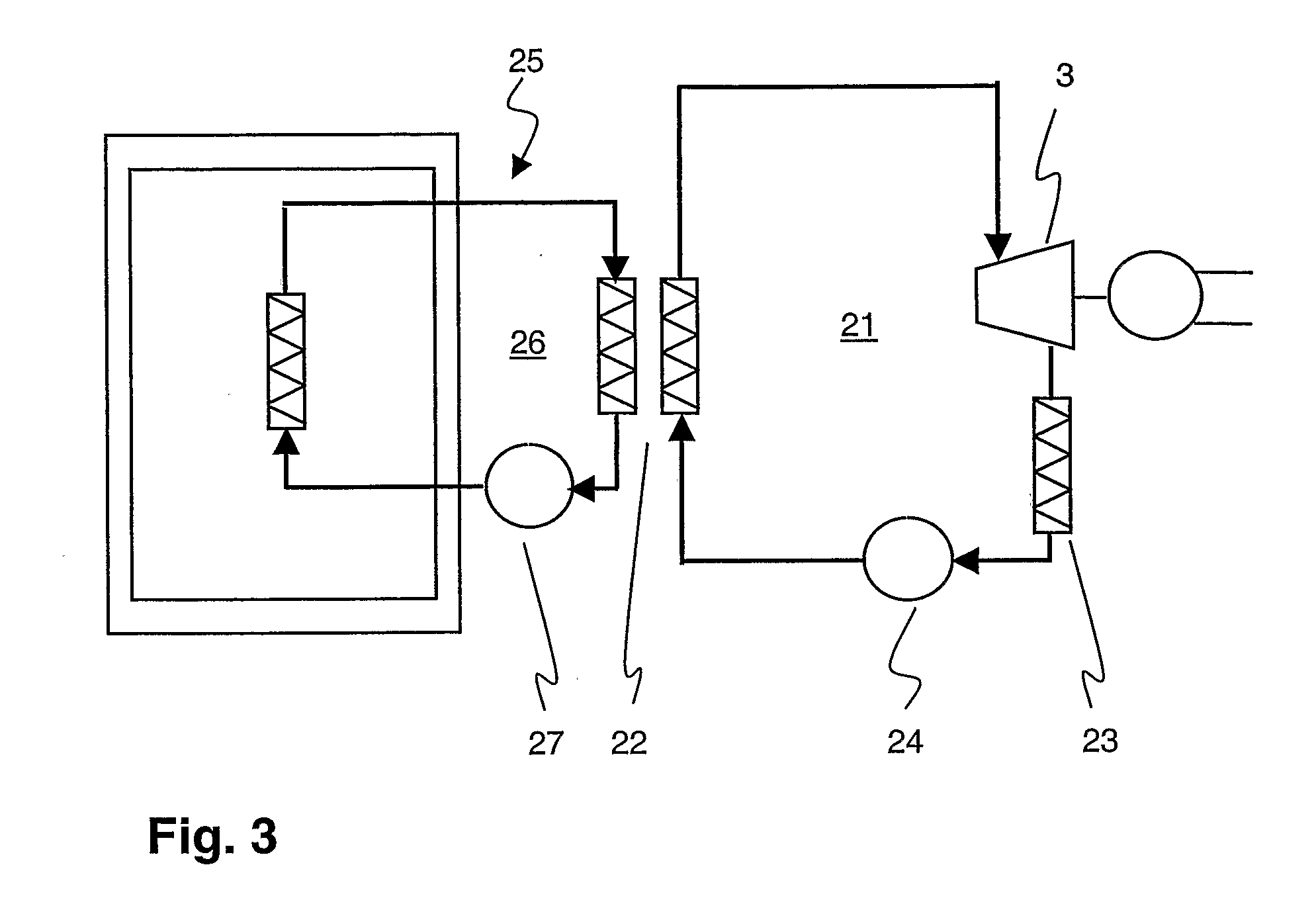
[0019]Preferably, the variable heat resistance is achieved through a transfer circuit coupled to and arranged between the heat storage device and the first working fluid circuit, and controlling the convective heat transfer in this transfer circuit. The latter is done e.g. by regulating the flow speed via a valve or a pump of a liquid metal (lead, sodium or silver) used as a transfer or auxiliary fluid. The temperature difference between the heat storage medium and the upper or optimum temperature of the working medium of the thermodynamic machine thus can be adapted to maximize both the heat content of the storage device and the efficiency of the conversion of heat to electricity.

Problems solved by technology

Furthermore, if periods of insufficient supply last very long, an energy storage unit of formidable size might be required to sustain power during these periods, in consequence, such power generation systems are often complemented with conventional power generation from fossil fuels which can be easily stored in large quantity.
Hydrostorage is the most developed large scale electric energy storage technology, but it is limited to few suitable geographic locations and large plant sizes.
While electrothermal energy storage seems to lack technical elegance, it is remarkable from an economic point of view, as it has a peculiar cost structure compared to other electrical energy storage technologies.
It has also moderate cost per kW (“conversion cost” or “power cost”).
Despite of the abovementioned advantages, electrothermal energy storage is yet no option for most applications, as the advantages are outweighed by the poor round-trip efficiency (from electrical back to electrical).

Method used


Image

  • Storing Thermal Energy and Generating Electricity
  • Storing Thermal Energy and Generating Electricity
  • Storing Thermal Energy and Generating Electricity

Examples


Embodiment Construction

[0010]It is therefore an objective of the invention to balance or equilibrate a time dependent discrepancy between an electricity demand and supply without adding too much system investment cost. This objective is achieved by a system for providing thermal energy to a thermodynamic machine and a method for generating electrical power according to claims 1 and 9. Further preferred embodiments are evident from the dependent patent claims.

[0011]According to the invention, a source of electrical power supplies electricity to a first heat generating means which converts the electricity into heat to be stored in a heat storage device. The heat is occasionally retrieved, via first heat transfer means, from the device and provided to a thermodynamic machine for generating electricity such as a thermal machine in expansion mode, i.e. a turbine, or a reciprocating engine, e.g. a Stirling engine. If the thermal energy thus retrieved is insufficient to meet the electricity demand, it is complem...


PUM


Abstract

Because the efficiency of the thermal energy storage technology is inherently restricted, its beneficial use is limited to very particular economic boundary conditions, i.e. a large difference between the value of electricity going into the unit and the value of electricity coming out of the unit. With the reduction in wind power equipment prices and the cost of fossil fuels and / or their combustion products this is occasionally the case for wind power. Wind is a free fuel and the value of wind power when there is too little load demand is essentially zero, and the value of wind power when there is demand is considerable indeed. Under these circumstances, a combination of electrothermal energy storage and combustion of (fossil) fuels as an auxiliary heat source provides for a cost efficient system for storing energy and an economical way of generating electricity.

Description

FIELD OF THE INVENTION[0001]The invention relates to the field of energy storage and generation of electricity. It departs from a system for providing thermal energy to a thermodynamic machine for generating electrical power as described in the preamble of claim 1 and a method for generating electrical power in response to an electrical power demand.BACKGROUND OF THE INVENTION[0002]Important renewable energy sources for generating electricity are intermittent by nature. Wind blows or does not, the sun shines or does not. If electric power generation from such intermittent energy sources has to be continuous, an energy storage unit is required where energy is stored during periods of abundant supply and retrieved from as electricity demand exceeds supply. Furthermore, if periods of insufficient supply last very long, an energy storage unit of formidable size might be required to sustain power during these periods, in consequence, such power generation systems are often complemented w...

Claims


Application Information

Patent Timeline
IPC IPC(8): F03G6/00F01K13/00F02C6/14F02C7/10F03D9/00F03D9/02
CPCF02C6/14F02C7/10F03D9/006F03D9/02F05B2220/60Y02E60/145Y02E10/46Y02E10/725F05D2220/60Y02E70/30F28D20/021F03D9/18F03D9/22Y02E10/72Y02E60/14Y02P90/50F03D9/255
Inventor OHLER, CHRISTIANCHARTOUNI, DANIELLAKNER, MARTIN
Owner ABB RES LTD
Learn More