Thermal container

a container and thermal insulation technology, applied in the direction of containers, liquid dispensing, packaged goods, etc., can solve the problem of spoilage of stored materials

Inactive Publication Date: 2002-09-19
ZUCKER HANS +2
View PDF0 Cites 79 Cited by
  • Summary
  • Abstract
  • Description
  • Claims
  • Application Information

AI Technical Summary

Benefits of technology

[0005] It is, therefore, a primary object of the invention to overcome, or at least minimize, the disadvantages of known thermal containers and of insulating components and thus to provide a storage or transport container operable at substantially constant temperatures over extended periods of time.
[0008] It is a further object of the invention to provide a light weight thermal container which is simple to manufacture.
[0009] A still further object of the invention is to provide a thermal container of the kind referred to which offers a favorable ratio of net weight to tare weight and of net volume to tare volume thereby to reduce materials and costs.
[0010] Another object of the invention is to provide a container of the kind referred to which in general avoids the need for liquefied nitrogen or similar coolant.

Problems solved by technology

Any undesirable changes in temperature may, and very often do, lead to spoiling of the stored material.

Method used


Image

  • Thermal container
  • Thermal container
  • Thermal container

Examples


example 2

[0085] A transport container 1 similar to Example 1 is provided, in accordance with the invention, with an insulation flange 48 which tightly and sealingly engages the internal tube or wall 15, the leg 42 and the lip 43 which in the area of the double-sine or S-shaped fillet 36 forms an annular cavity. In the present context, "annular cavity" is intended to connote a chamber similar to a body resulting from moving a planar figure along a closed curve--for instance by revolving about an axis disposed in the plane of the figure without intersecting it. In the embodiment shown in FIG. 6, the figure chosen resembles the segment of a circle limited by one of the curves of the S-shaped fillet 36 and the marginal surface 50 of the insulation flange 48, the rotational axis of the figure being the axis of symmetry of the transport container 1. In accordance with the invention, the annular cavity 49 of the container described need not be shaped like a segment of a circle; it may have other pr...

example 3

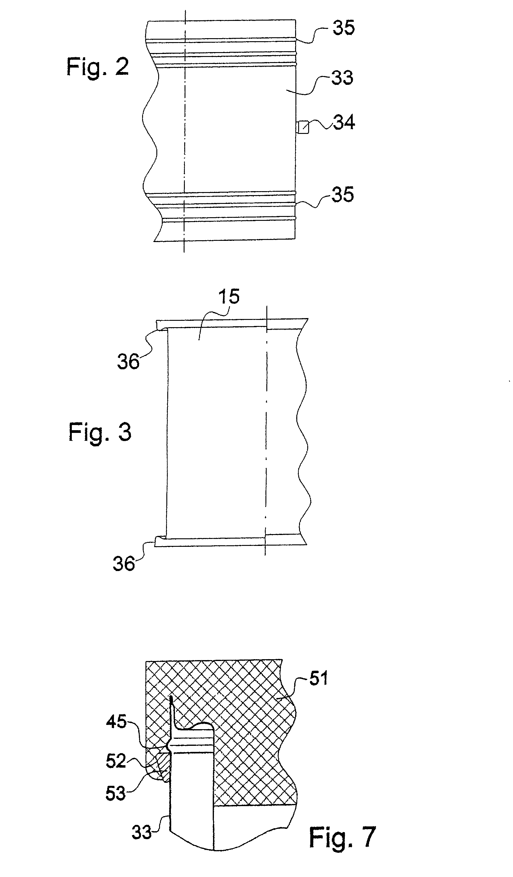
[0090] A transport container 1 substantially similar to that of Example 1 differs structurally at the rim of the openings of the hollow body, i.e. at the connections between its internal tube 15 and its external tube 33. FIG. 7 offers a sectional view of the area of a container rim of the embodiment to be described.

[0091] An annular flange 51 is provided close to the outer circumference of the external tube 33 of the casing 30. A gap 52 in the flange 51 is filled with a suitable adhesive, for instance a silicon adhesive, after the flange 51 has been attached to the casing 30. This results in a particularly sturdy connection between the flange 51 behind the bead 45 in the external wall 33. Such a structure is suitable for closing either end of the tubular hollow body.

example 4

[0092] A transport container 1 generally similar to Example 1 has a differently structured rim at the openings of the hollow body. The transitional zone between its internal tube 15 and its external tube 33 differs as may be seen from the four configurations depicted in FIG. 8. At their top and bottom ends the internal tube 15 and the external tube 33 converge approximately semi-circularly and are joined by a welded seam 44. In addition, the internal tube 15 is provided with outwardly and inwardly directed beads 45 and 54. This results in a reduced material thickness and, hence, provides for a heat path of extended length.

[0093] Three further examples shown in FIG. 8 depict variations of the connections between internal tube 15 and external tube 33. Prior to being joined by the welding seam 44, the two tubes are shaped in different ways. Each one of these variations does ensure at least two degrees of freedom between the tubes and thus accommodates the desired properties of resilien...


PUM


Abstract

A thermal insulation container for storing materials at predetermined temperatures over extended periods including thermal energy storage units and means for substantially eliminating thermal conductors and providing improved insulation properties by mechanically absorbing temperature induced frictional forces. Highly efficient vacuum thermal insulators embedded within components of the container contribute significantly to its superior temperature maintaining characteristics.

Description

BACKGROUND OF THE INVENTION[0001] 1. Field of the Invention[0002] The invention, in general, relates to a novel thermal insulation container wherein materials may be stored at a predetermined substantially constant temperature over extended periods of time and, more particularly, to a container provided with vacuum insulation, thermal energy storage units, at least one storage chamber, various highly insulating components and a temperature monitoring, storing and data transmission device. Containers of the kind here under consideration are suitable for storing their contents not only at high temperatures but also, and perhaps more importantly, at very low or cryogenic levels of temperature.[0003] 2. The Prior Art[0004] Various usually double-walled containers for storing different media or materials, such as, for instance, low boiling point liquefied gasses, are well known. Also, containers are known for transporting or storing materials at temperatures ranging from very hot to very...

Claims


Application Information

Patent Timeline
Patent Type & Authority Applications(United States)
IPC IPC(8): B65D81/18B65D81/38F17C3/04F17C3/06F17C3/08F17C13/00F25D3/00F25D3/06
CPCB65D81/18B65D81/3806F17C3/04F17C3/06F17C3/08F17C13/001F17C2203/0391F25D3/00F25D3/06F25D2201/1282F25D2201/14F25D2331/804
Inventor ZUCKER, HANSSOMMER, WERNERWORF, MATTHIAS
Owner ZUCKER HANS
Why Eureka
Try Eureka