
A system for generating a virtual image for a wearer

Pending Publication Date: 2021-07-29
ESSILOR INT CIE GEN DOPTIQUE
View PDF0 Cites 0 Cited by
  • Summary
  • Abstract
  • Description
  • Claims
  • Application Information

AI Technical Summary

Benefits of technology

The patent describes a system that can create a virtual image for a person wearing the system. This system compensates for the person's poor vision, by adjusting the image so that it is sharp and clear when it reaches the person's eye. This results in a better quality virtual image for the person to see.

Problems solved by technology

However, such prior art eyewear equipment fails to consider the ophthalmic prescription of the wearer.
However, the inventors have observed that the absence of ophthalmic prescription consideration reduces visual sharpness, for instance when ametropia becomes high, or even when ametropia is low, it introduces additional loss in image sharpness.

Method used


Image

  • A system for generating a virtual image for a wearer

Examples


Embodiment Construction

[0042]The invention relates to a system, for example an eyewear equipment, for generating a virtual image of a wearer.

[0043]In the reminder of the description, terms like «up», «bottom», «horizontal», «vertical», «above», «below», «front», «rear» or other words indicating relative position may be used. These terms are to be understood in the wearing conditions of the system or eyewear equipment of the invention.

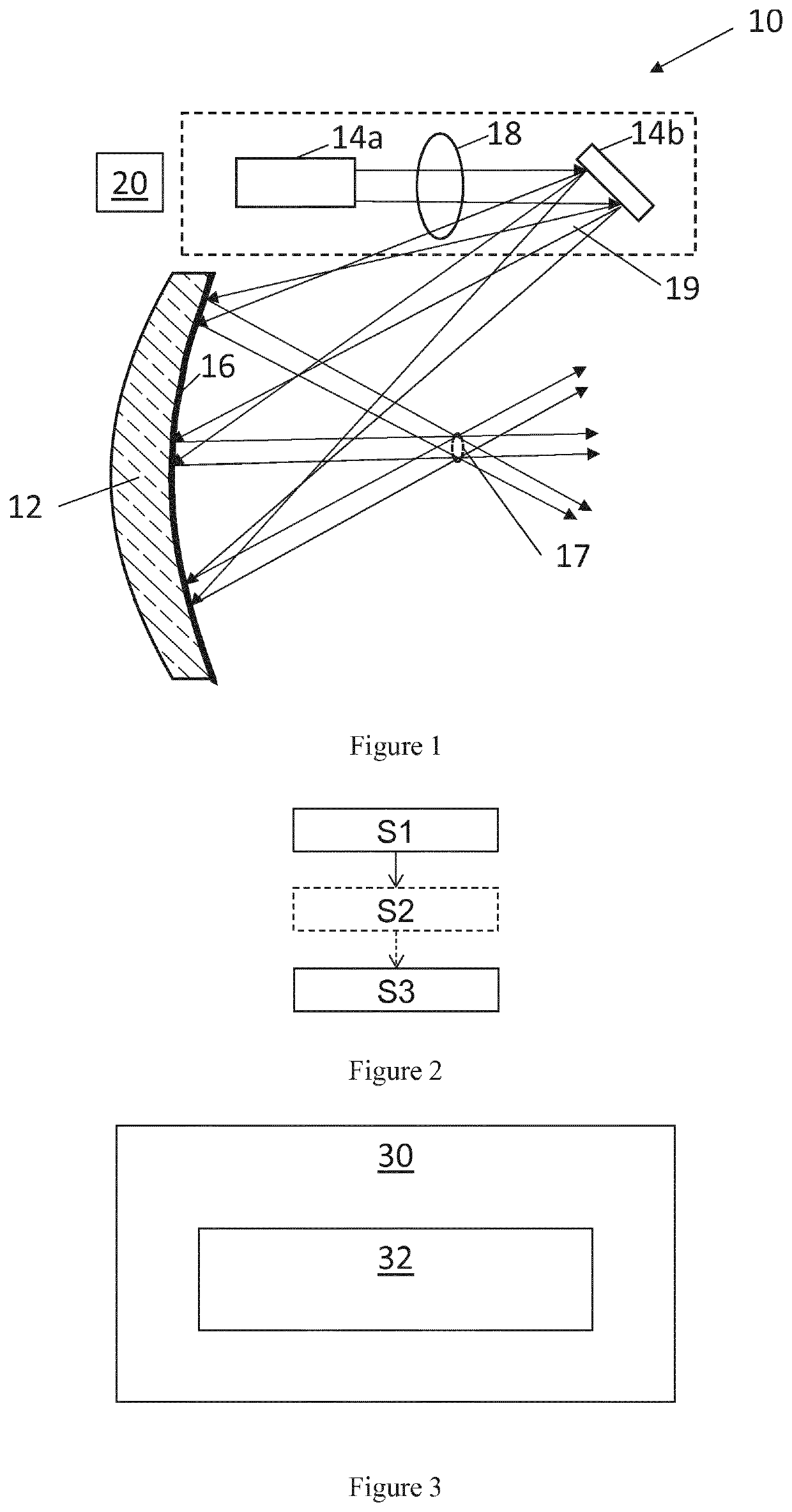
[0044]As illustrated on FIG. 1, the invention relates to system 10 for generating a virtual image for a wearer. Preferably, the system 10 of the invention is part of an eyewear equipment intended to be worn by a wearer.

[0045]The system according to the invention comprises at least:

[0046]a lens 12,

[0047]a directive light source 14a, 14b,

[0048]a reflecting element 16,

[0049]a dynamical optical element 18, and

[0050]a memory 20 storing prescription data relative to the prescription of the wearer.

[0051]The lens 12 provides vision of real scene to the wearer and has refractive powe...


PUM


Abstract

A system for generating a virtual image for a wearer includes: a lens providing vision of a real scene and having refractive power related to the prescription of the wearer, a directive light source that emits directive light beams to create the virtual image, a reflecting element positioned on or in the lens that receives and redirects the directive light beams emitted by the directive light source toward a convergence area of an eye of the wearer, a dynamical optical element for modifying the received light beams, and a memory storing prescription data relative to the prescription of the wearer, the dynamical optical element modifying the light beams at the convergence area so as to compensate at least partly the prescription of the wearer.

Description

TECHNICAL FIELD[0001]The invention relates to a system for generating a virtual image for a wearer, a method for generating a virtual image for a wearer and a computer program product.BACKGROUND OF THE INVENTION[0002]Patent application WO 2016 / 081888 discloses an eyewear equipment including a holographic mirror and a micro display to provide a virtual image to the wearer of the eyewear equipment.[0003]The micro display includes a movable / changeable power lens, that allows, in synchronization with a light source, to modifying the focal point of the light source, so that the light rays issued from the light source and after reflection on a holographic mirror are collimated.[0004]Such eyewear equipment provides improved virtual images to the wearer. For instance, the focal distance of the virtual image can match the focal distance of a targeted object in the real scene; this is convenient for augmented reality purpose.[0005]However, such prior art eyewear equipment fails to consider th...

Claims


Application Information

Patent Timeline
IPC IPC(8): G02B27/01G02C7/14
CPCG02B27/0172G02B2027/0187G02B2027/0178G02C7/14G02C7/086
Inventor ROPTIN, VINCENT
Owner ESSILOR INT CIE GEN DOPTIQUE
Learn More