Chemical solution pump and chemical solution administration device
a chemical solution and pump technology, applied in the direction of flow monitors, intravenous devices, other medical devices, etc., can solve the problems of fluid change, resistance force is not always constant, and the pump actually receives a resistance force, so as to achieve accurate discharging of chemical solution and constant amount
- Summary
- Abstract
- Description
- Claims
- Application Information
AI Technical Summary
Benefits of technology
Problems solved by technology
Method used
Image
Examples
first embodiment
[0064]Hereinafter, a first embodiment of a chemical solution pump and a chemical solution administration device according to the aspect of the present invention will be described with reference to the drawings.
Chemical Solution Administration Device
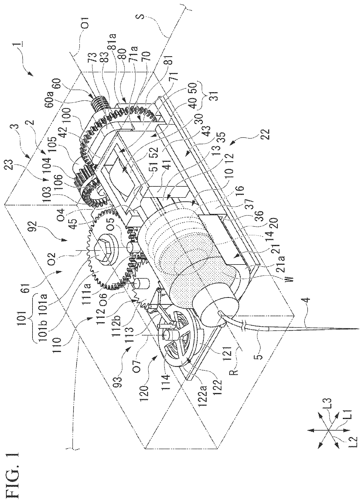
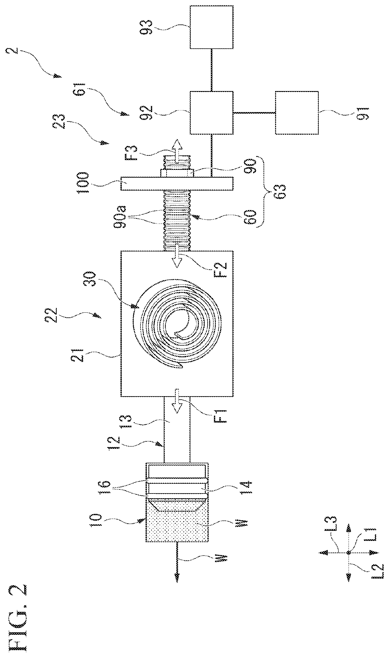
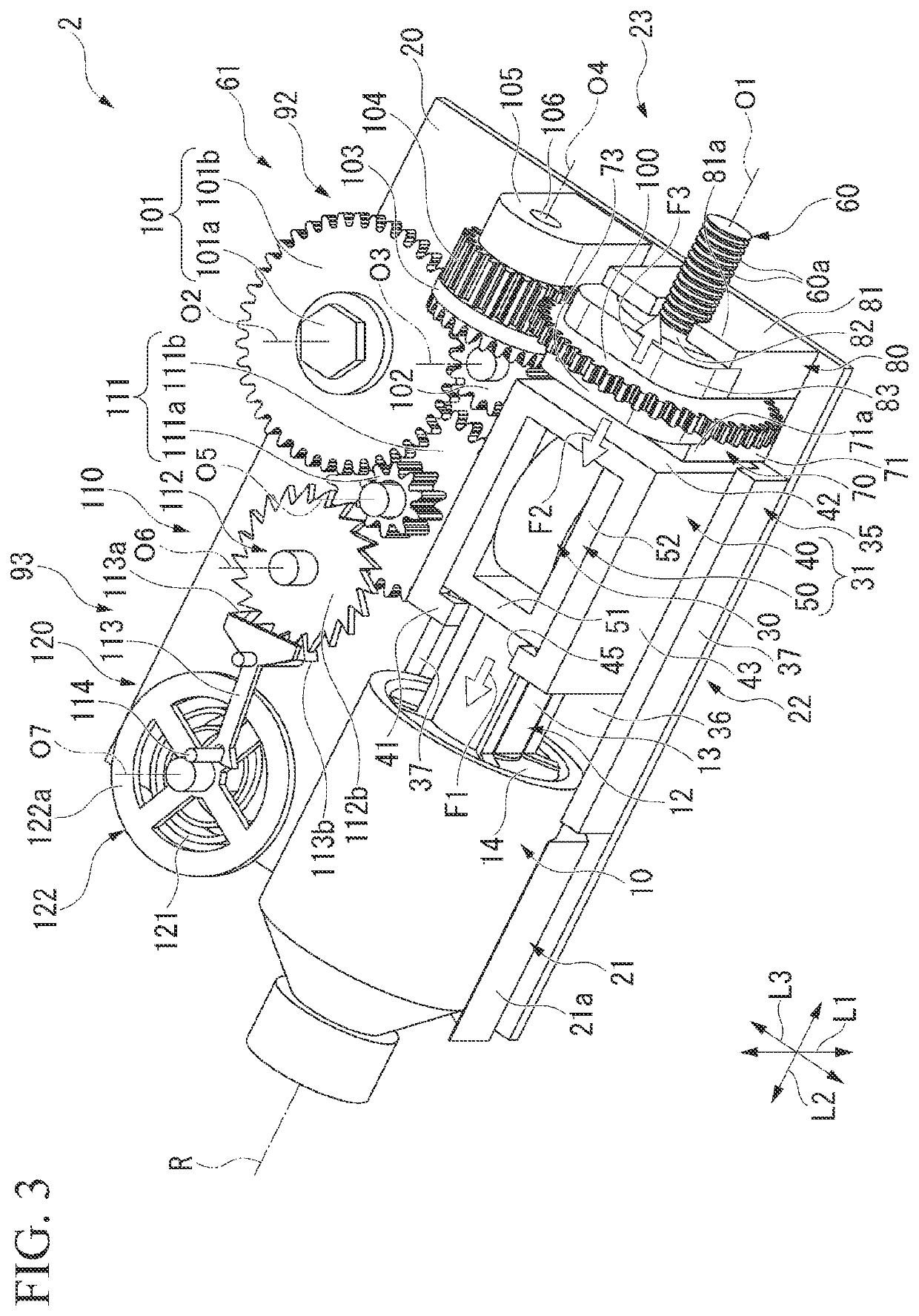
[0065]As illustrated in FIG. 1, a chemical solution administration device 1 of the present embodiment includes a chemical solution pump 2 that discharges a chemical solution W from a syringe 10 filled with the chemical solution W, and a main body case 3 internally accommodating the chemical solution pump 2, and mountable on a user's body surface (living body surface according to the present invention) S.
[0066]The chemical solution W is not particularly limited, and for example, insulin may be used. In this case, the chemical solution administration device 1 functions as an insulin administration device, and the chemical solution pump 2 functions as an insulin pump.
[0067]For example, the main body case 3 is configured so that a case body a...
second embodiment
[0172]Next, a second embodiment of a chemical solution pump according to the aspect of the present invention will be described with reference to the drawings. In the second embodiment, the same reference numerals will be assigned to configuration elements the same as configuration elements in the first embodiment, and description thereof will be omitted.
[0173]As illustrated in FIG. 13, a chemical solution pump 130 of the present embodiment includes a switching mechanism 131 that switched between stopping and starting transmission of power from the mainspring 91 to the nut member 90.
[0174]The switching mechanism 131 is a mechanism for adding a so-called start and stop function, and is provided in an intermediate portion of a transmission route in which the power generated by the mainspring 91 is transmitted to the nut member 90. In the present embodiment, the switching mechanism 131 is provided adjacent to the balance with hairspring 122 forming the speed controller 120.
[0175]As illu...
modification example of second embodiment
[0205]In the above-described second embodiment, the second magnet 138 is attached to the holding wall portion 137 side. However, the present invention is not limited to this case. For example, as in the first magnet 136, the second magnet 138 may be attached to the second operation surface 132b of the oscillator plate 132. In this case, the holding wall portion 137 side may be the magnetic body.
[0206]Furthermore, in the above-described second embodiment, a configuration is adopted so that the rotation of the balance with hairspring 122 is restricted by using the magnetic force between the first magnet 136 and the balance wheel 122a. However, the present invention is not limited to a case of using the magnetic force. For example, the first magnet 136 may be omitted, the first operation surface 132a may be pressed against the outer peripheral surface of the balance wheel 122a, and a frictional force acting between the first operation surface 132a and the balance wheel 122a may be used...
PUM
 Abstract
Description
Claims
Application Information
 - R&D
- Intellectual Property
- Life Sciences
- Materials
- Tech Scout
- Unparalleled Data Quality
- Higher Quality Content
- 60% Fewer Hallucinations
Browse by: Latest US Patents, China's latest patents, Technical Efficacy Thesaurus, Application Domain, Technology Topic, Popular Technical Reports.
© 2025 PatSnap. All rights reserved.Legal|Privacy policy|Modern Slavery Act Transparency Statement|Sitemap|About US| Contact US: help@patsnap.com


