Check patentability & draft patents in minutes with Patsnap Eureka AI!

Magnetostriction element and magnetostriction-type vibration powered generator using same

Pending Publication Date: 2021-08-05
PANASONIC INTELLECTUAL PROPERTY MANAGEMENT CO LTD
View PDF2 Cites 0 Cited by
  • Summary
  • Abstract
  • Description
  • Claims
  • Application Information

AI Technical Summary

Benefits of technology

The present disclosure describes a magnetostriction element and a magnetostriction-type vibration powered generator that can produce a lot of power and have a high power density.

Problems solved by technology

However, the needs for wirings and service time, and the cost make it difficult to provide power supplies for these proliferating numbers of devices.
However, in the magnetostriction-type vibration powered generator above, the stress exerted on the magnetostriction element in response to an external force (vibration) applied within a horizontal plane in the cantilever beam structure is greater at the fixed end than at the free end, and this creates a stress distribution as a result of the stress not being exerted throughout the magnetostriction element in a uniform fashion.
That is, the power density E (power output P per volume) is too small to achieve the high output (high power output) needed for IoT.

Method used


Image

  • Magnetostriction element and magnetostriction-type vibration powered generator using same
  • Magnetostriction element and magnetostriction-type vibration powered generator using same
  • Magnetostriction element and magnetostriction-type vibration powered generator using same

Examples


example 1

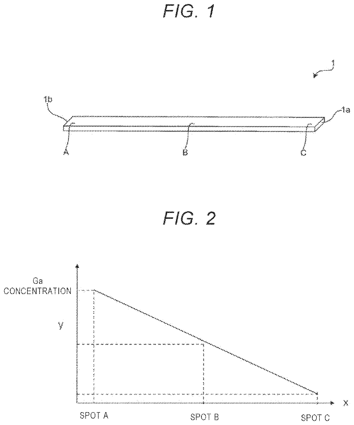
[0061]In Example 1, a plate-shaped FeGa-alloy magnetostriction element was produced that had varying Ga concentrations along its longitudinal direction. The magnetostriction element was then measured for magnetic flux density under no applied stress and under applied compressional stress, and changes occurring in magnetic flux density were confirmed.

Production of Magnetostriction Element

[0062]In order to produce an FeGa-alloy magnetostriction element of

[0063]Example 1-1, iron (purity 99.999%) and gallium (purity 99.999%) were weighed with an electronic balance. The content of each element in alloy specimens was measured and adjusted by EPMA analysis.

[0064]Specimens were grown using a high-frequency dielectric heating CZ furnace. A dense alumina crucible measuring 45 mm in outer diameter (ϕ) was disposed inside a graphite crucible having an inner diameter ϕ of 50 mm, and weighed 400 g of Fe and Ga was supplied as raw materials of each alloy specimen. The crucibles charged with the ra...

example 2

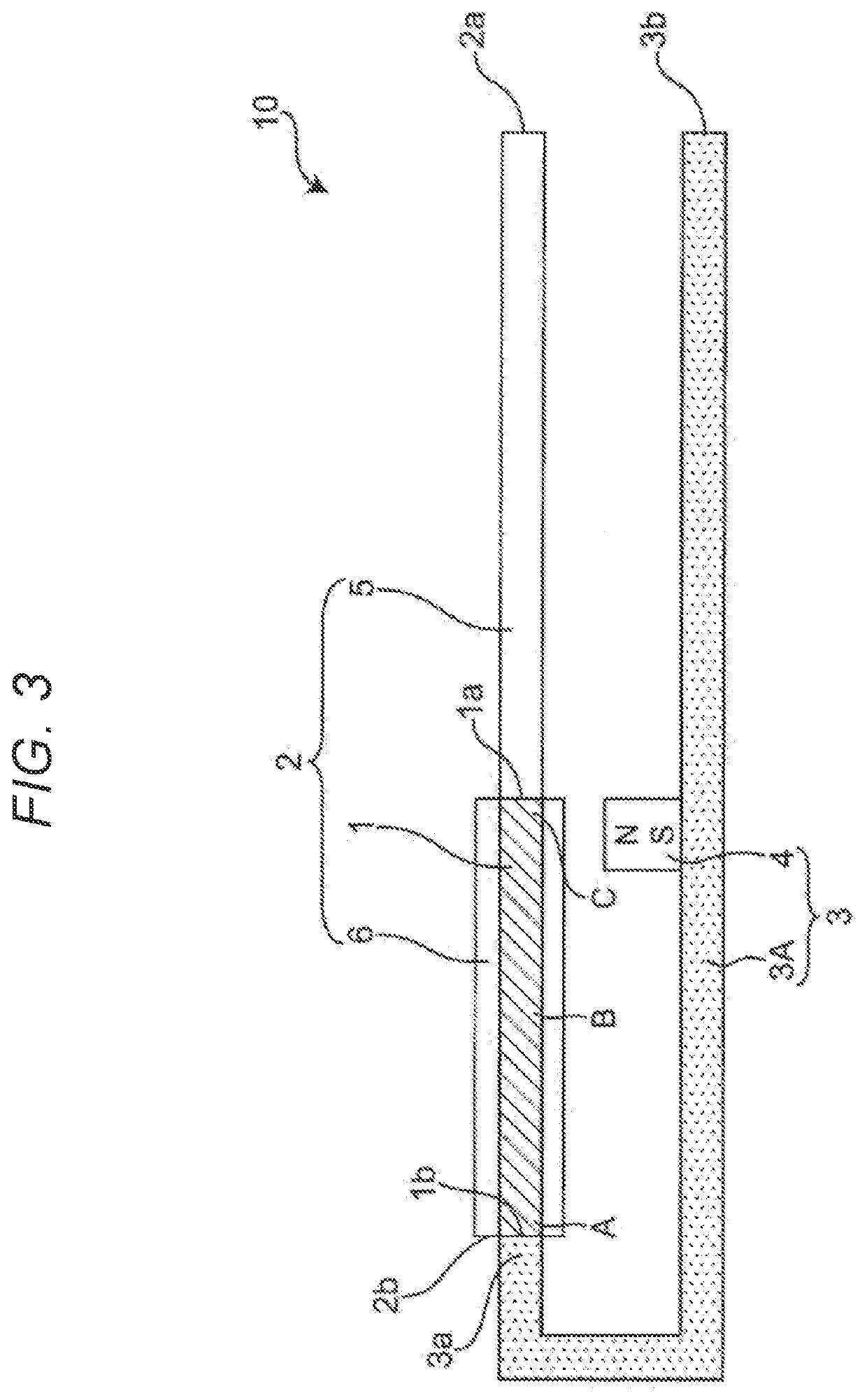
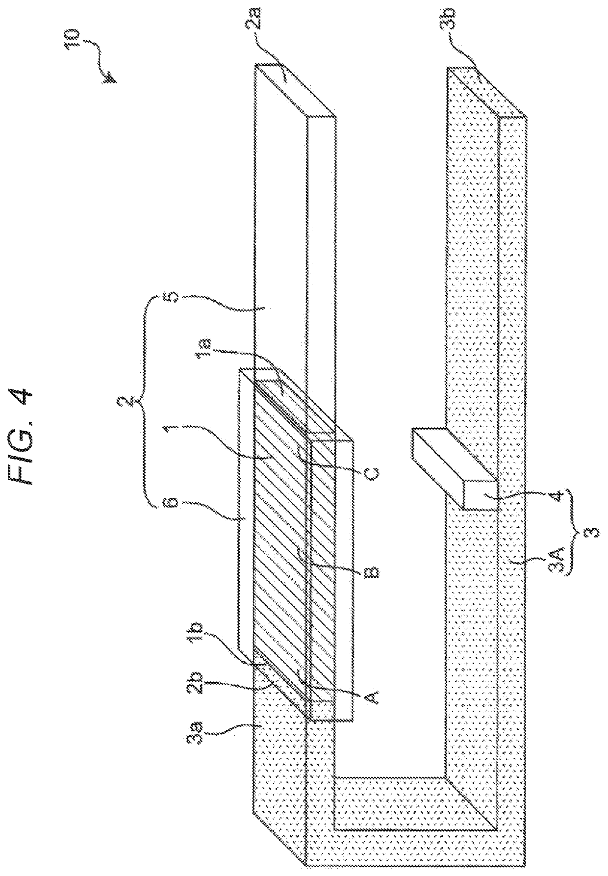
[0074]In Example 2, magnetostriction elements of various Ga concentrations were produced in the same manner as for the FeGa-alloy magnetostriction element of Example 1-1. These were then measured for magnetic flux density under no applied stress and under applied compressional stress, and changes occurring in magnetic flux density were confirmed. For the evaluation of the power density of each magnetostriction element, the magnetostriction element was installed in a magnetostriction-type vibration powered generator of the configuration shown in FIGS. 3 and 4, and measured for power density.

[0075]The magnetostriction elements used for measurement had a plate shape as in Example 1-1. The Ga concentrations in the magnetostriction elements had the values shown in Table 2 at spots A, B, and C as measured by EPMA analysis (the rest is the Fe concentration (at %)). In Examples 2-1 to 2-4, the magnetostriction elements had varying Ga concentrations at spots A, B, and C. The magnetostriction...

example 3

[0084]In Example 3, the Ga concentration of the FeGa alloy of Example 1-1 was varied, and a trace amount of Sm, Cu, or C was added to produce magnetostriction elements. For the evaluation of the power density of the magnetostriction element, the magnetostriction element was installed in the magnetostriction-type vibration powered generator in the same manner as in Example 2, and the power density was measured to confirm the effectiveness of adding these additional elements.

Evaluation of Power Density in Magnetostriction-Type Vibration Powered Generator Equipped with Magnetostriction Element

[0085]The magnetostriction elements used for measurement had a plate shape as in Example 1-1. The Ga concentrations (at %) at spots A, B, and C of the magnetostriction elements had the values shown in Tables 3-1 and 3-2 (spot A: 19; spot B: 17.5; spot C: 16) and in Tables 4-1 and 4-2 (spot A: 17; spot B: 15.5; spot C: 14) as measured by EPMA analysis. Tables 3-1 and 3-2 and Tables 4-1 and 4-2 also...


PUM

PropertyMeasurementUnit
Pressureaaaaaaaaaa
Pressureaaaaaaaaaa
Magnetic flux densityaaaaaaaaaa

Abstract

A magnetostriction-type vibration powered generator including a power generating section and a frame joined to the power generating section. The power generating section includes a diaphragm formed of non-magnetic material and disposed at a first end of the power generating section, a magnetostriction element disposed at a second end of the power generating section; and a coil wrapped around the magnetostriction element along the longitudinal direction. The frame includes a frame body formed of a magnetic material and joined to a second end of the power generating section. A magnet is provided on the frame body so as to face the magnetostriction element of the power generating section.

Description

CROSS-REFERENCE TO RELATED APPLICATIONS[0001]The present application is a divisional application of U.S. application Ser. No. 16 / 460,145 filed on Jul. 2, 2019 and claims the benefit of foreign priority of Japanese patent application 2018-160992 filed on Aug. 30, 2018, the contents of which are incorporated herein by reference.TECHNICAL FIELD[0002]The technical field relates to a magnetostriction element formed of a magnetostrictive material, and to a magnetostriction-type vibration powered generator using same.BACKGROUND[0003]Recent years have seen the arrival of the Internet of things (IoT), a world where “things” equipped with autonomous communication functions automatically control one another by exchanging information. The spread of IoT means a society with increasing numbers of IoT devices featuring communication functions. IoT devices, such as sensors, require a power supply to operate. However, the needs for wirings and service time, and the cost make it difficult to provide ...

Claims


Application Information

Patent Timeline
IPC IPC(8): H02N2/18H01L41/12H01L41/20
CPCH02N2/188C22C38/002H01L41/20H01L41/125H10N35/101H10N35/85
Inventor NAKAMURA, TAICHISAKAI, KAZUKI
Owner PANASONIC INTELLECTUAL PROPERTY MANAGEMENT CO LTD
Features
  • R&D
  • Intellectual Property
  • Life Sciences
  • Materials
  • Tech Scout
  • Unparalleled Data Quality
  • Higher Quality Content
  • 60% Fewer Hallucinations
Learn More