Square-shaped insert for bar-peeling and insert-holder tool for same

Pending Publication Date: 2021-08-12
ISCAR LTD
View PDF10 Cites 0 Cited by
  • Summary
  • Abstract
  • Description
  • Claims
  • Application Information

AI Technical Summary

Benefits of technology

[0077]As will become clear below the versatile design of the bar-peeling insert allows it to be used as both a roughing bar-peeling insert or a finishing bar-peeling insert.
[0078]While FR 2 483 819 appears to show an embodiment in which identical inserts are used together, the lack of a significant wiper sub-edge seems to

Problems solved by technology

Such operations are characterized as very “rough” machining operations with large chip loads and resulting high forces on the cutting insert and cutting assembly, as well as instabil

Method used


Image

  • Square-shaped insert for bar-peeling and insert-holder tool for same
  • Square-shaped insert for bar-peeling and insert-holder tool for same
  • Square-shaped insert for bar-peeling and insert-holder tool for same

Examples


Example

[0111]Referring to FIG. 1, a bar-peeling tool assembly 10 
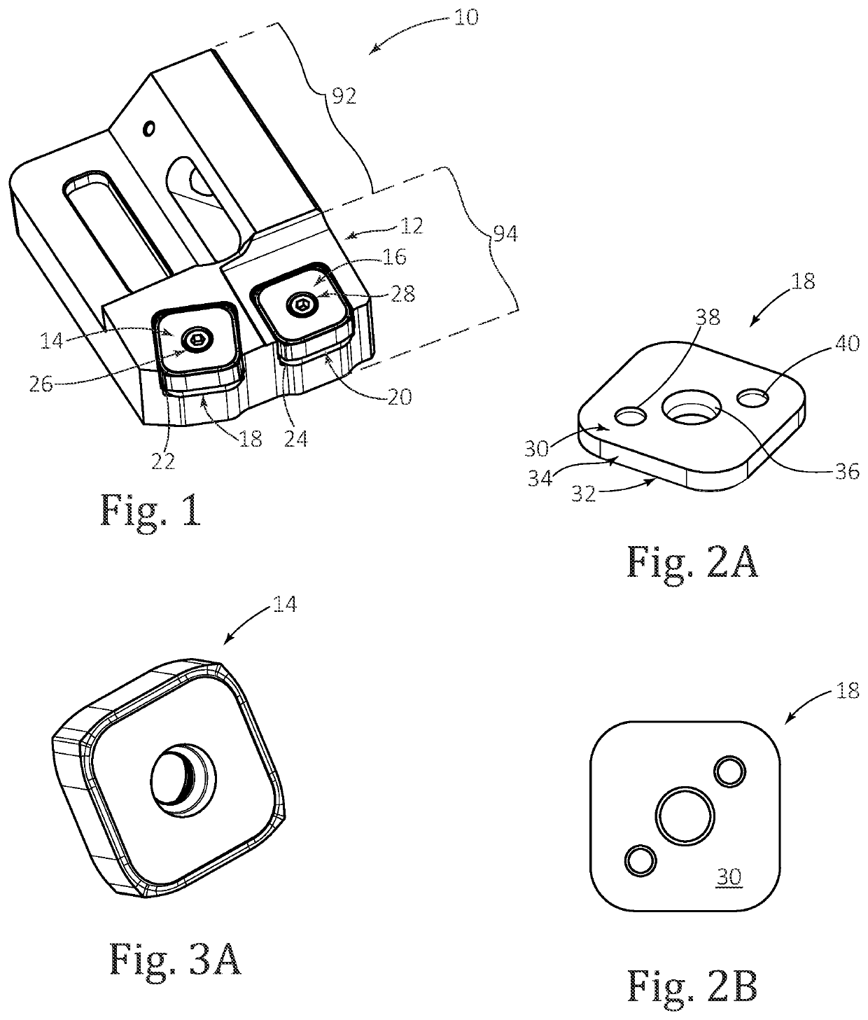
is shown. The assembly 10 comprises an insert-holder 12, and two identical inserts 14, 16 that in their respective positions and orientations in the insert-holder 12 function as a roughing insert 14 and a finishing insert 16, identical first and second shims 18, 20 respectively located between the roughing insert 14 and the finishing insert 16 and respective first and second insert pockets 22, 24 to which they are mounted.

[0112]The roughing insert 14 is secured to the first insert pocket 22 by a screw 26. The finishing insert 16 is similarly secured to the second insert pocket 22 by another screw 28.

[0113]Referring also to FIGS. 2A, 2B, 3A and 4A, only the first shim 18 out of the two identical shims will be described.

[0114]The first shim 18 is made of cemented carbide and has a planar (or, alternatively stated, plate) shape. More precisely, the first shim 18 comprises opposing first and second shim sides 30, 32 and a shim pe...


PUM

PropertyMeasurementUnit
Angleaaaaaaaaaa
Lengthaaaaaaaaaa
Radiusaaaaaaaaaa

Abstract

A square-shaped bar-peeling insert and insert-holder designed with pockets to hold two such square-shaped inserts. Each insert has four peripheral sub-surfaces and corners. Between each adjacent pair of corners is a cutting edge which includes a straight wiper sub-edge and two at least partially curved peeling sub-edges respectively located on opposing sides of the wiper sub-edge. The corners of the insert are inwardly disposed relative to an imaginary square formed by the sub-edges.

Description

RELATED APPLICATIONS[0001]The present application claims priority to U.S. Provisional Patent Application No. 62 / 975,259 filed Feb. 12, 2020. The contents of the aforementioned application are incorporated by references in their entirety.FIELD OF THE INVENTION[0002]The subject matter of the present application relates to a bar-peeling insert, insert-holder and tool assembly comprising same. More particularly, the subject matter is directed to a square-shaped bar-peeling insert and insert-holder for holding the square-shaped insert.BACKGROUND OF THE INVENTION[0003]Bar-peeling is a machining operation which differs from both a standard turning operation in which the workpiece is rotated and from a standard milling operation in which the cutting tool rotates and the workpiece is static. Generally speaking, in a bar-peeling operation an elongated bar is moved (relatively) in an axial direction through an area where a bar-peeling cutting tool assembly is located, and a peeling head rotate...

Claims


Application Information

Patent Timeline
IPC IPC(8): B23B5/12B23B27/16
CPCB23B5/12B23B2200/0476B23B27/1622B23B2220/40B23B2220/445B23B2200/0471
Inventor DAKWAR, AMJADHEN, DANIEL
Owner ISCAR LTD
Why Eureka
Try Eureka