Mirror cutting needle type probe and processing method

A processing method and needle technology, which is applied in the field of test probes, can solve the problems of easy contamination of the needle and large roughness of the needle, and achieve the effect of not easy to stain, small roughness, and good finish

Pending Publication Date: 2022-07-22
渭南木王智能科技股份有限公司
0 Cites 0 Cited by

AI-Extracted Technical Summary

Problems solved by technology

[0003] The first object of the present invention is to provide a mirror-cut needle-type probe, which solves the prob...

Method used

[0029] Different from the existing probes, the needle 3 of the present invention is provided with a plurality of serrations 4, and the plurality of serrations 4 can adapt to test points of different shapes to ensure good contact between the needle 3 and the test points. In addition, the surface of the sawtooth 4 is all mirror-polished, the roughness is small, relatively smooth, and it is not easy to be stained, which can ensure that it always maintains a high degree of cleanliness during long-term use. Therefore, the service life of the probe is greatly extended.
[0031] The four sawtooths 4 are symmetrically arranged in two pairs, so that the design can increase the contact area and can contact with test points of different shapes.
[0033] The sawtooth 4 is trihedral and prismatic to facilitate mirror processing, and the operation is relatively convenient.
[0035] The two needles 3 are in contact with the testing machine respectively at the test point, and after being extruded, they are elastically contracted by the elastic member 2 to ensure good contact without breakin...

Abstract

The invention discloses a mirror cutting needle type probe which comprises a needle tube, an elastic piece is arranged in the needle tube, needle heads are inserted into the two ends of the needle tube respectively, the tail portions of the two needle heads abut against the two ends of the elastic piece respectively, a plurality of sawteeth are arranged on the head portion of each needle head in a claw shape, and the surface of each sawtooth is subjected to mirror polishing. The invention relates to a mirror cutting needle type probe, which solves the problems that the needle of the existing probe is large in roughness and is easy to stain after being used for a long time. The invention further discloses a machining method of the mirror cutting needle type probe.

Application Domain

Technology Topic

PhysicsCutting needle +5

Image

  • Mirror cutting needle type probe and processing method
  • Mirror cutting needle type probe and processing method

Examples

  • Experimental program(1)

Example Embodiment

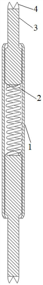
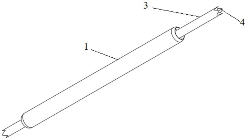
[0025] The following describes in detail the embodiments of the present invention, examples of which are illustrated in the accompanying drawings, wherein the same or similar reference numerals refer to the same or similar elements or elements having the same or similar functions throughout. The embodiments described below with reference to the accompanying drawings are exemplary and are only used to explain the present invention, and should not be construed as a limitation of the present invention.
[0026] In the description of the present invention, if it is described that the first and the second are only for the purpose of distinguishing technical features, it should not be understood as indicating or implying relative importance or implicitly indicating the number of indicated technical features or implicitly indicating The order of the indicated technical features.
[0027] In the description of the present invention, unless otherwise clearly defined, words such as setting, installation, connection should be understood in a broad sense, and those skilled in the art can reasonably determine the specific meaning of the above words in the present invention in combination with the specific content of the technical solution.
[0028] like figure 1 and figure 2 As shown in the figure, a mirror-cut needle probe of the present invention includes a needle tube 1, an elastic member 2 is arranged in the needle tube 1, and needle heads 3 are respectively inserted at both ends of the needle tube 1, and the tails of the two needle heads 3 are respectively abutted on the At both ends of the elastic member 2, the head of each needle 3 is provided with a plurality of serrations 4 in a claw shape, and the surface of each serration 4 is mirror-polished.
[0029] Different from the existing probe, the needle 3 of the present invention is provided with a plurality of serrations 4, and the plurality of serrations 4 can be adapted to test points of different shapes, so as to ensure that the needle 3 can form a good contact with the test points. In addition, the surfaces of the saw teeth 4 are all mirror-polished, and the roughness is small and relatively smooth. Therefore, the service life of the probe is greatly extended.
[0030] combine figure 2 , In a mirror cutting needle probe of the present invention, the number of saw teeth 4 is four, which are arranged at an equal angle of 90°.
[0031] The four serrations 4 are arranged symmetrically in two pairs, so that the design can increase the contact area and can make contact with test points of different shapes.
[0032] combine figure 2 , in a mirror cutting needle probe of the present invention, the serrations 4 are in the shape of three-sided prisms.
[0033] The serrations 4 are in the shape of three-sided prisms, which are convenient for mirror processing and are more convenient to operate.
[0034] combine figure 2 , in a mirror cutting needle probe of the present invention, the elastic member 2 is a compression spring.
[0035] The two needles 3 are respectively in contact with the testing point and the testing machine. After being squeezed, they are elastically contracted by the elastic member 2, which can ensure good contact and no disconnection.
[0036] like figure 1 As shown, in a mirror-cut needle probe of the present invention, both ends of the needle tube 1 are formed with a constriction, the outer diameter of the tail of the needle 3 is larger than the outer diameter of the head, and the tail of the needle 3 is limited within the constriction.
[0037] By processing the constriction at both ends of the needle tube 1, the tail of the needle head 3 can be limited in the needle tube 1, and the operation is relatively convenient.
[0038] like figure 1 As shown, in a mirror cutting needle probe of the present invention, the tail of the needle 3 is provided with a tapered surface, and the end of the elastic member 2 is sleeved on the tapered surface.
[0039] Such a design can ensure a large contact surface between the elastic member 2 and the tail portion of the needle 3 to form a good contact.
[0040] like figure 1 As shown, a processing method of a mirror-cut needle probe of the present invention is specifically implemented according to the following steps:
[0041] Step 1, mirror cutting the needle 3 to process a plurality of saw teeth 4;
[0042] Step 2, insert a needle 3 from one end of the needle tube 1;
[0043] Step 3, put the compression spring into the needle tube 1;
[0044] Step 4, insert another needle 3 from the other end of the needle tube 1;
[0045] Step 5, encapsulate the two needles 3 in the needle tube 1 .
[0046] like figure 1 As shown, in a processing method of a mirror-cut needle probe of the present invention, in step 1, the number of saw teeth 4 is four, and they are arranged at an equal angle of 90°.
[0047] The four serrations 4 are arranged symmetrically in two pairs, so that the design can increase the contact area and can make contact with test points of different shapes.
[0048] like figure 1 As shown, in the processing method of a mirror-cut needle probe of the present invention, in step 1, the saw teeth 4 are in the shape of three-sided prisms.
[0049] The serrations 4 are in the shape of three-sided prisms, which are convenient for mirror processing and are more convenient to operate.
[0050] like figure 1 As shown, in the processing method of a mirror-cut needle probe of the present invention, in step 5, encapsulating the two needles 3 in the needle tube 1 is specifically: forming a constriction at both ends of the needle tube 3, The tail of 3 is limited in the needle tube 1.
[0051] By processing the constriction at both ends of the needle tube 1, the tail of the needle head 3 can be limited in the needle tube 1, which is convenient for operation and low in cost.
[0052] Therefore, compared with the prior art, the present invention can adapt to more test objects by changing the shape of the traditional probe needle to form a serrated claw head, thereby further expanding the use scene of the probe. In addition, because the surface of the sawtooth is in a mirror state, the roughness is small, the finish is good, the tin removal performance is good, and it is not easy to be stained, so that the test accuracy is high, the service life is greatly improved, and the use cost of the test probe is reduced. .
[0053] The foregoing specification shows and describes several preferred embodiments of the invention, but as previously mentioned, it should be understood that the invention is not limited to the form disclosed herein and should not be construed as an exclusion of other embodiments, but may be used in a variety of other Combinations, modifications and environments are possible within the scope of the inventive concepts described herein, from the above teachings or from skill or knowledge in the relevant fields. However, modifications and changes made by those skilled in the art do not depart from the spirit and scope of the invention, and should fall within the protection scope of the appended claims of the invention.

PUM

no PUM

Description & Claims & Application Information

We can also present the details of the Description, Claims and Application information to help users get a comprehensive understanding of the technical details of the patent, such as background art, summary of invention, brief description of drawings, description of embodiments, and other original content. On the other hand, users can also determine the specific scope of protection of the technology through the list of claims; as well as understand the changes in the life cycle of the technology with the presentation of the patent timeline. Login to view more.

Similar technology patents

Method for manufacturing titanium-and-titanium alloy high-pressure gas cylinder

PendingCN110465780AEliminate wrinklesReduce roughnessVessel manufacturingPressure vesselsTitaniumHigh pressure
Owner:BAOJI FANMEI MATERIAL TECH

Classification and recommendation of technical efficacy words

  • Good finish
  • Reduce roughness

Collapsible ISO container-type modular shelter

InactiveUS20060277836A1Good insulating abilityGood finishBuilding roofsSpecial buildingModularityConstruction industry
Owner:CHAZYN FABIO

Wear-resistant easy-to-cut brass pipe material and method of using same to manufacture brass pipe

ActiveCN104894430AEliminate metal transverse crack defectsGood finishAlloy elementBrass
Owner:JINTIAN COPPER GROUP CORP NINGBO
Why Eureka
Try Eureka