Hydrofoil unit for a mobile offshore apparatus

a technology for offshore apparatus and hydrofoil, which is applied in the direction of propulsive element steering, vessel construction, hull, etc., can solve the problems of inability to perform respective maneuvers, complex maintenance and/or repair procedures of corresponding offshore apparatus, and disadvantages of previously described landing processes

Active Publication Date: 2021-08-19
RWE RENEWABLES GMBH
View PDF0 Cites 3 Cited by
  • Summary
  • Abstract
  • Description
  • Claims
  • Application Information

AI Technical Summary

Benefits of technology

[0011]Therefore, the object of the application is to provide a device for a mobile offshore apparatus, in particular, for a watercraft, for a landing at (to) a further offshore apparatus, which allows a safe landing at the further offshore apparatus even with (in) a swell with higher wave heights.

Problems solved by technology

In offshore wind energy systems with a plurality of stationary offshore apparatuses, such as offshore wind turbines, offshore substations, offshore measuring stations, etc., in particular, maintenance and / or repair procedures for a corresponding offshore apparatus are complex and cost-intensive.
However, the previously described landing process has disadvantages.
In particular, the respective maneuver is only feasible up to a specific wave height (e.g., approximately 1 to 1.5 m (significant)).
If the swell exceeds this wave height, the landing procedure can no longer be performed in a safe manner due to the increased movement of the mobile offshore apparatus caused by this swell.
This prevents a safe landing at the further offshore apparatus.
From the specific (significant) wave height (e.g. approximately 1 to 1.5 m), there is a risk of slipping of the bow of the catamaran construction.
This is accompanied by corresponding risks of injury to the personnel.
Accordingly, with such mobile offshore apparatuses, landings and thus the performing of maintenance processes and / or repair processes are not possible with a swell where the specific (significant) wave height (e.g. approx.
This leads to an unwanted prolongation of maintenance and / or repair processes.
This is particularly problematic if the operation of the offshore apparatus to be repaired and / or maintained (e.g. a wind turbine) has to be interrupted until the corresponding maintenance and / or repair process is completed.
The disadvantages of these apparatuses are the complex construction and the considerable weight of these systems, so that they can only be used on larger ships.

Method used


Image

  • Hydrofoil unit for a mobile offshore apparatus
  • Hydrofoil unit for a mobile offshore apparatus
  • Hydrofoil unit for a mobile offshore apparatus

Examples


Embodiment Construction

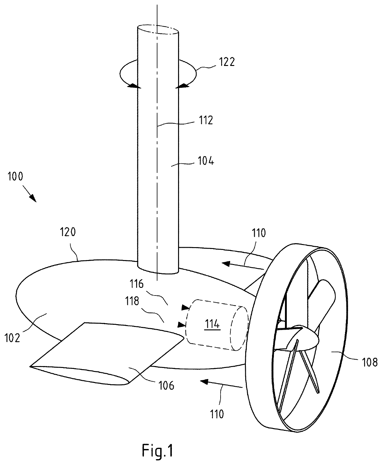
[0093]FIG. 1 shows a schematic perspective view of an embodiment of a hydrofoil device 100 according to the present application. As can be seen from FIG. 1, the illustrated hydrofoil device 100 comprises a base body 102, two hydrofoils 106, a connecting unit 104 and a flow generator 108.

[0094]The hydrofoils 106 are mounted to the outer side surfaces of the base body 102. For example, the hydrofoils 106 may be mounted by a suitable joining method (e.g., welding, bonding, etc.). It is also conceivable that a base body and the at least one hydrofoil are formed integrally.

[0095]Presently, a flow generator 108, in particular, in the form of a propeller or impeller, is disposed at a longitudinal end of the base body 102. The flow generator 108 may be driven by a drive unit 114. In the present, preferred embodiment, the drive unit 114 is arranged within the base body 102. In particular, the drive unit 114 may be integrated in the housing 120 of the base body 102. Alternatively, the drive u...


PUM


Abstract

A hydrofoil device for a mobile offshore apparatus, in particular, a watercraft. The hydrofoil device includes at least one base body with at least one connection unit which is arranged for connecting the hydrofoil device to the mobile offshore apparatus. At least one hydrofoil is arranged on the base body. At least one flow generator is arranged to generate a flow around the hydrofoil. The hydrofoil device in its intended use is rotatable at least about a substantially vertical axis of rotation depending on at least one control data set that can be provided.

Description

[0001]CROSS-REFERENCE TO RELATED PATENT APPLICATIONS[0002]This patent application is a continuation of International Application No. PCT / EP2019 / 077499, filed on Oct. 10, 2019, which claims the benefit of priority to German Patent Application No. 10 2018 127 650.8, filed Nov. 6, 2018, the entire teachings and disclosures of both applications are incorporated herein by reference thereto.FILED OF INVENTION[0003]The application relates to a hydrofoil device for a mobile offshore apparatus, in particular, a watercraft. In addition, the application relates to a mobile offshore apparatus and a method for operating a mobile offshore apparatus.BACKGROUND[0004]Wind power systems and wind farms, respectively, with a plurality of wind turbines are known. Here, a wind turbine is configured to convert the kinetic energy of the wind into electrical energy. Offshore wind energy systems and offshore wind farms, respectively, are increasingly installed due to the higher wind safety and / or the higher ...

Claims


Application Information

Patent Timeline
Patent Type & Authority Applications(United States)
IPC IPC(8): B63B1/28B63H25/42
CPCB63B1/283B63H25/42B63B39/08B63B1/107Y02E10/727Y02E10/72
Inventor ROSEN, JOHANNES
Owner RWE RENEWABLES GMBH
Why Eureka
Try Eureka