
Stabilized, water-jet, slurry apparatus and method

a technology of slurry and water jet, which is applied in the field of stabilizing water jet and slurry apparatus and methods, can solve the problems of ineffective suspension slurry, significant disadvantages of using such a device, and inability to stop and go with slurry, etc., and achieve the effect of improving excavation efficiency and effective shelf li

Pending Publication Date: 2021-08-26
H2O TECH
View PDF0 Cites 0 Cited by
  • Summary
  • Abstract
  • Description
  • Claims
  • Application Information

AI Technical Summary

Benefits of technology

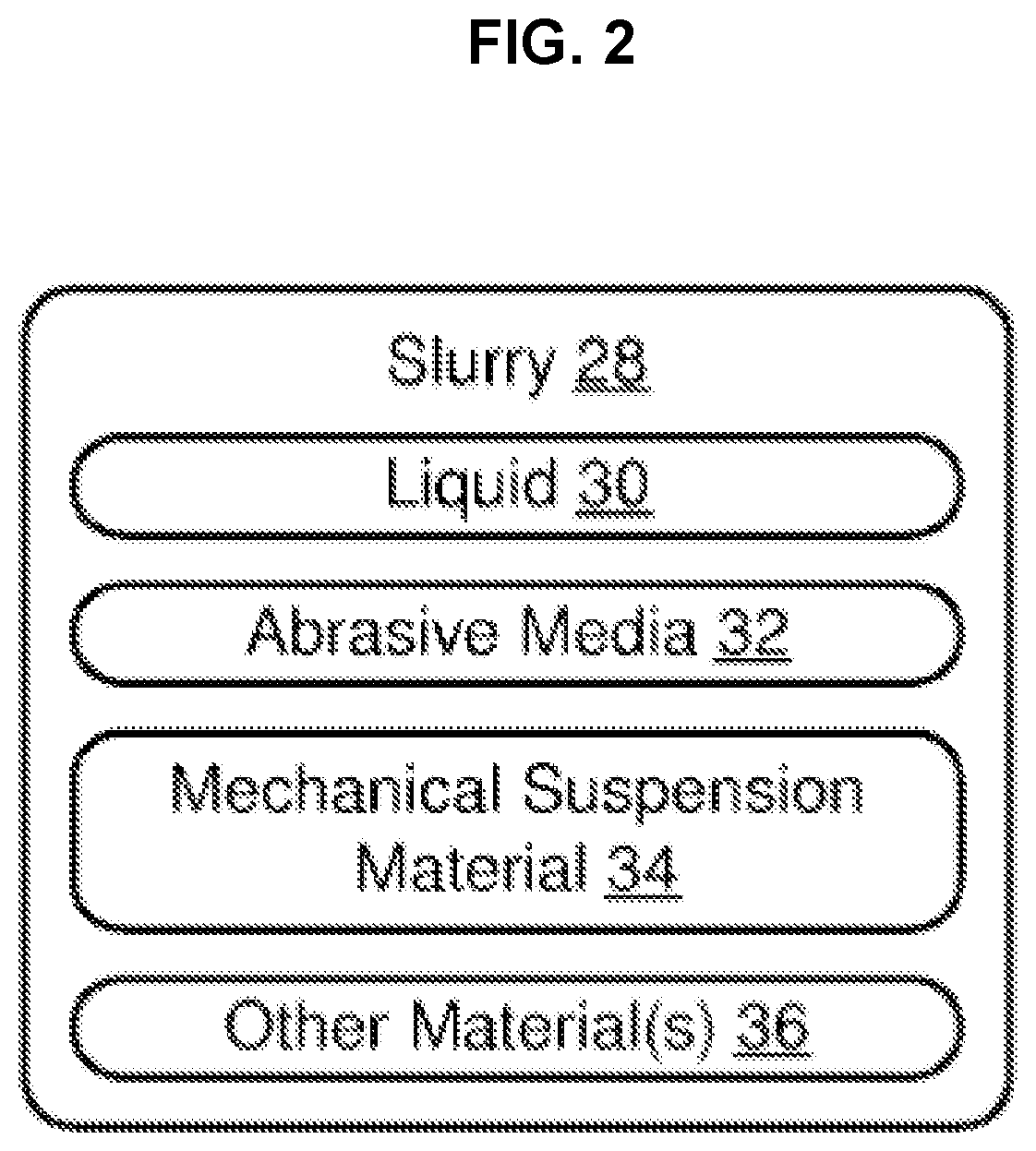
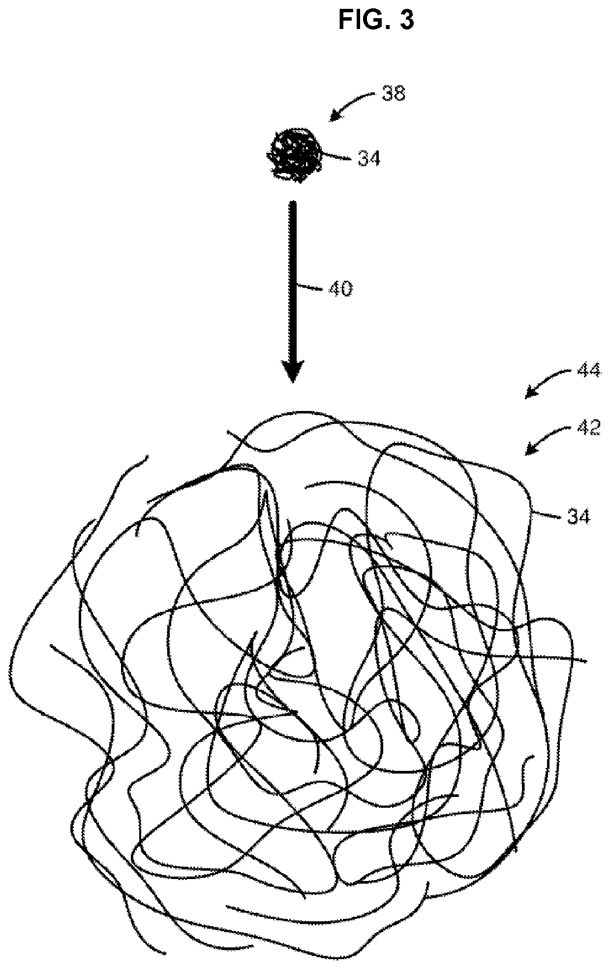
The present invention is a slurry that includes a liquid, abrasive media, and mechanical suspension material. The liquid allows the slurry to flow through a delivery system while the abrasive media helps to speed up the excavation or drilling process. The mechanical suspension material prevents the abrasive particles from migrating within the liquid, which makes the slurry more stable and provides a longer shelf life.

Problems solved by technology

Suspension slurries have not been effective for several reasons.
A principal problem is setting out.
Thus, industrial, dental, mining, drilling, and other examples, of cutting are not typically able to stop and go with a slurry.
Nevertheless, the problems to be solved span the range of industrial uses of cutting slurries.
However, the use of such a device has significant disadvantages.
For example, use of a rotary drill may damage the enamel of a tooth, which may weaken the structure of the tooth.
Due to size limitations, use of a rotary drill often requires the removal of considerably more healthy material than would otherwise be necessary.
Moreover, patients often experience discomfort from the grinding and vibrations that accompany use of a rotary drill.
While such systems can be effective for shallow cavities, they take too long to drill below the outer enamel layer of the tooth and into softer tissues.
However, the adoption of laser systems has been slowed by their high cost.
However, such systems can be hampered or limited in certain ways, primarily due to the rapidity with which particles precipitate out of the water, causing clogs and other problems.

Method used


Image

  • Stabilized, water-jet, slurry apparatus and method
  • Stabilized, water-jet, slurry apparatus and method
  • Stabilized, water-jet, slurry apparatus and method

Examples


Embodiment Construction

[0022]It will be readily understood that the components of the present invention, as generally described and illustrated in the drawings herein, could be arranged and designed in a wide variety of different configurations. Thus, the following more detailed description of the embodiments of the system and method of the present invention, as represented in the drawings, is not intended to limit the scope of the invention, as claimed, but is merely representative of various embodiments of the invention. The illustrated embodiments of the invention will be best understood by reference to the drawings, wherein like parts are designated by like numerals throughout.

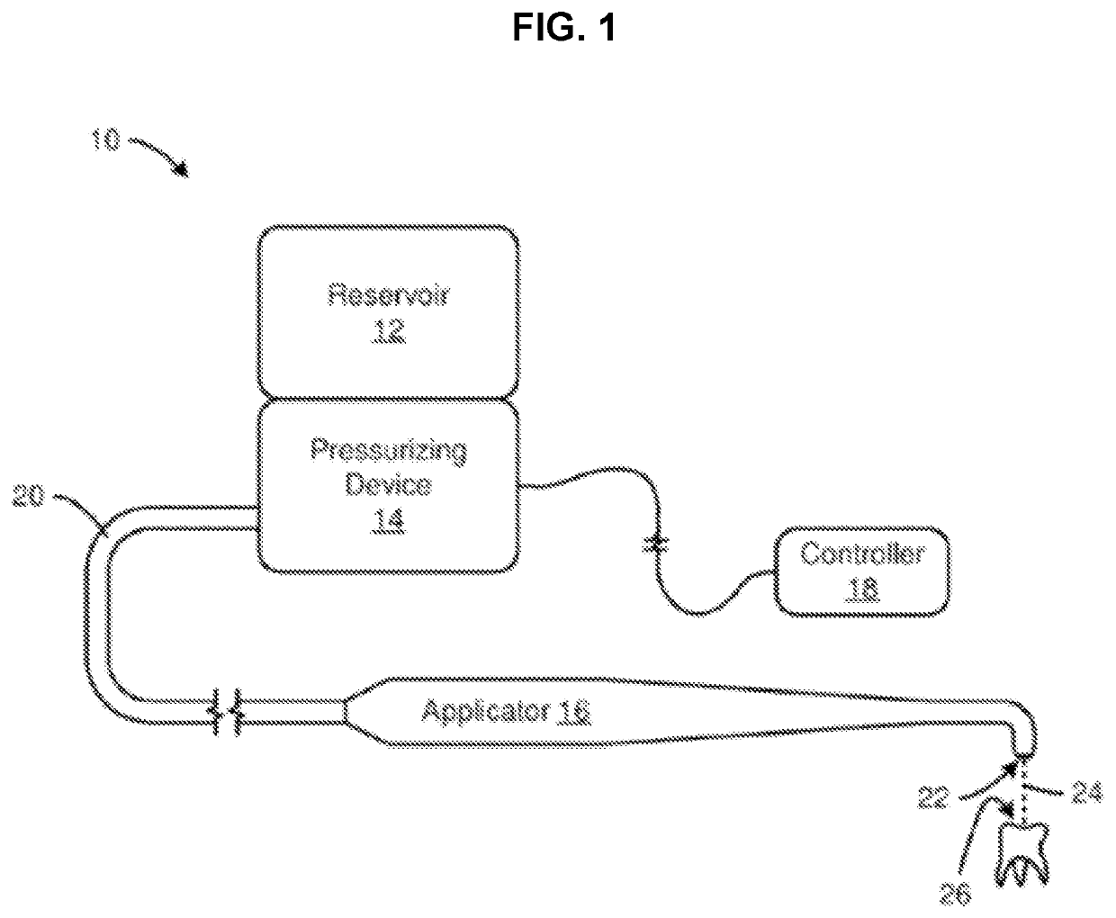
[0023]Referring to FIG. 1, a slurry in accordance with the present invention may be delivered or applied to a subject surface by a delivery system 10. A delivery system 10 may have any suitable configuration. In selected embodiments, a delivery system 10 may include a reservoir 12, a pressurizing device 14, an applicator 16, a c...


PUM

PropertyMeasurementUnit
effective diameteraaaaaaaaaa
exit velocityaaaaaaaaaa

Abstract

A method for removing dental material is disclosed. The method may include suspending, by a hydrated polymeric material, a quantity of abrasive media. The hydrated polymeric material and suspended abrasive media may then be pressurized. Accordingly, an abrasive stream may be formed by expelling, under pressure, the hydrated polymeric material and suspended abrasive media from a nozzle. The abrasive stream may be precisely applied to a tooth to abrade the enamel or dentin thereof as a drilling instrumentality.

Description

CROSS-REFERENCE TO RELATED APPLICATIONS[0001]This application is a continuation of U.S. patent application Ser. No. 13 / 938,385, filed on Jul. 10, 2013, which is incorporated by reference herein in its entirety.TECHNICAL FIELD[0002]This invention relates to cutting solid materials and, more particularly, to novel systems and methods for manufacturing and using a slurry abrasive.BACKGROUND[0003]Stone cutting relies on diamond-coated saws, polycrystalline diamond compacts, girt blasting, and the like. Suspension slurries have not been effective for several reasons. A principal problem is setting out. Thus, industrial, dental, mining, drilling, and other examples, of cutting are not typically able to stop and go with a slurry. Instead, they must mix abrasive at the point of use.[0004]Herein, dental drilling will be used as an example. It is one of the most demanding applications. Precision and timing are particularly rigorous. Likewise, control is critical, and must accommodate instanta...

Claims


Application Information

Patent Timeline
Patent Type & Authority Applications(United States)
IPC IPC(8): A61C3/025B24C1/04B24C11/00C09K3/14
CPCA61C3/025C09K3/1463B24C11/00B24C1/045
Inventor NELSON, TIMOTHY D.HEATON, DAREN N.
Owner H2O TECH
Learn More