
Device and method for extending the lifetime of a battery in a tire pressure sensor

a tire pressure sensor and battery technology, applied in the field of tire pressure sensors, can solve the problems of laborious process of replacing the battery of the tire pressure sensor, less than the life span of many automobiles and trucks, and the effective life of the battery may be even shorter. the effect of the battery li

Inactive Publication Date: 2007-08-21
HONDA MOTOR CO LTD
View PDF7 Cites 8 Cited by
  • Summary
  • Abstract
  • Description
  • Claims
  • Application Information

AI Technical Summary

Benefits of technology

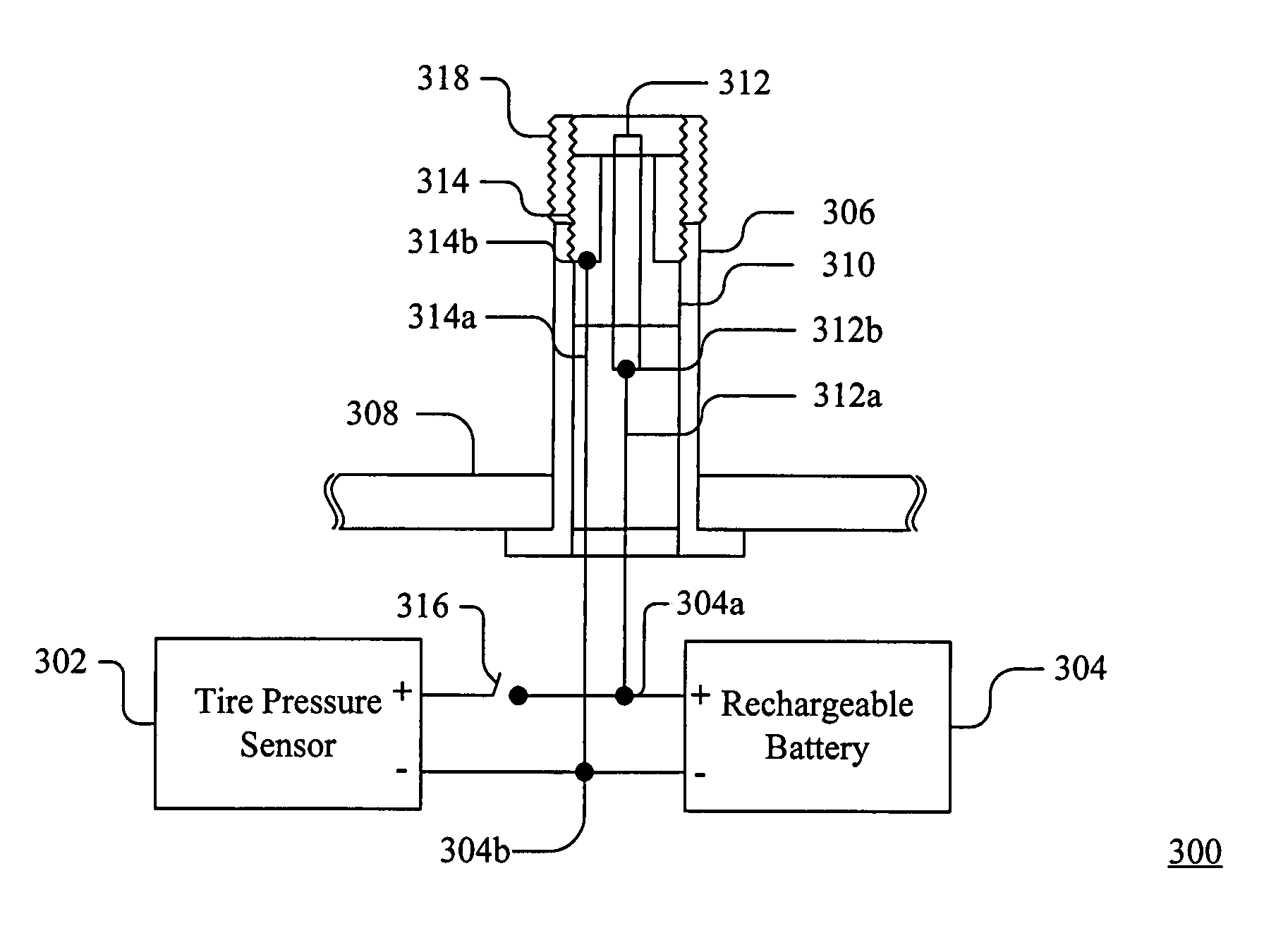
The present invention is about a device, method, and system for recharging the battery of a tire pressure sensor through the tire valve. This allows for regular servicing of the battery without having to remove the tire. The device includes an electrode and a switch for selectively supplying power to the electrode for charging the battery. The system includes a tire pressure sensor, a rechargeable battery, and a valve stem assembly with electrodes for accepting electrical power for recharging the battery. The invention also includes a centrifugal switch and a method for replacing a valve stem. The technical effects of the invention include extended battery life, improved reliability, and reduced maintenance costs.

Problems solved by technology

The lifetime of these long-life batteries, however, is five to ten years, which is less than the life span of many automobiles and trucks.
The effective lifetime of these batteries may be even shorter, because it is not desirable to run the battery down to such an extent that the tire pressure sensor system fails before the battery is replaced.
Furthermore, replacing a tire pressure sensor battery is a labor-intensive process, involving, e.g., the removal of the tire from the wheel.
These approaches, however, are difficult to model statistically and therefore guarantee a reliable battery lifetime that is commensurate with the life span of the vehicle under a wide range of uses.
Another problem with these approaches is that the usefulness of the tire pressure sensor is curtailed.
As another example, when the transmission of tire pressure information is limited to certain, rare conditions, the driver of the vehicle cannot be provided with real-time information on the pressure of the vehicle's tires.

Method used


Image

  • Device and method for extending the lifetime of a battery in a tire pressure sensor
  • Device and method for extending the lifetime of a battery in a tire pressure sensor
  • Device and method for extending the lifetime of a battery in a tire pressure sensor

Examples


Embodiment Construction

[0020]A device and method for extending the lifetime of a battery of a tire pressure sensor disposed in a tire are described. In the following description, for purposes of explanation, numerous specific details are set forth in order to provide a thorough understanding of the present invention. It is apparent to one skilled in the art, however, that the present invention may be practiced without these specific details or with an equivalent arrangement. In some instances, well-known structures and devices are shown in block diagram form in order to avoid unnecessarily obscuring the present invention.

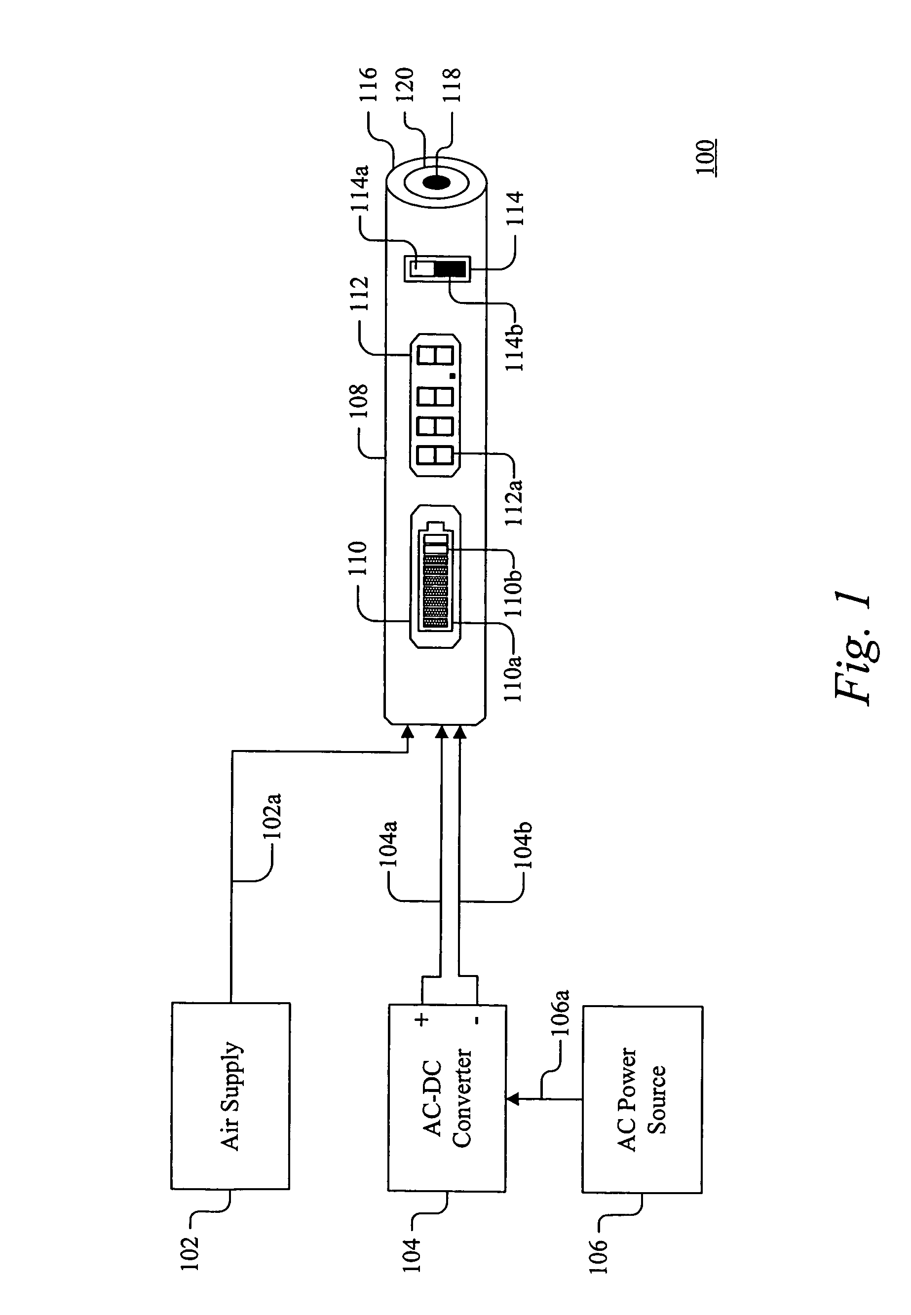
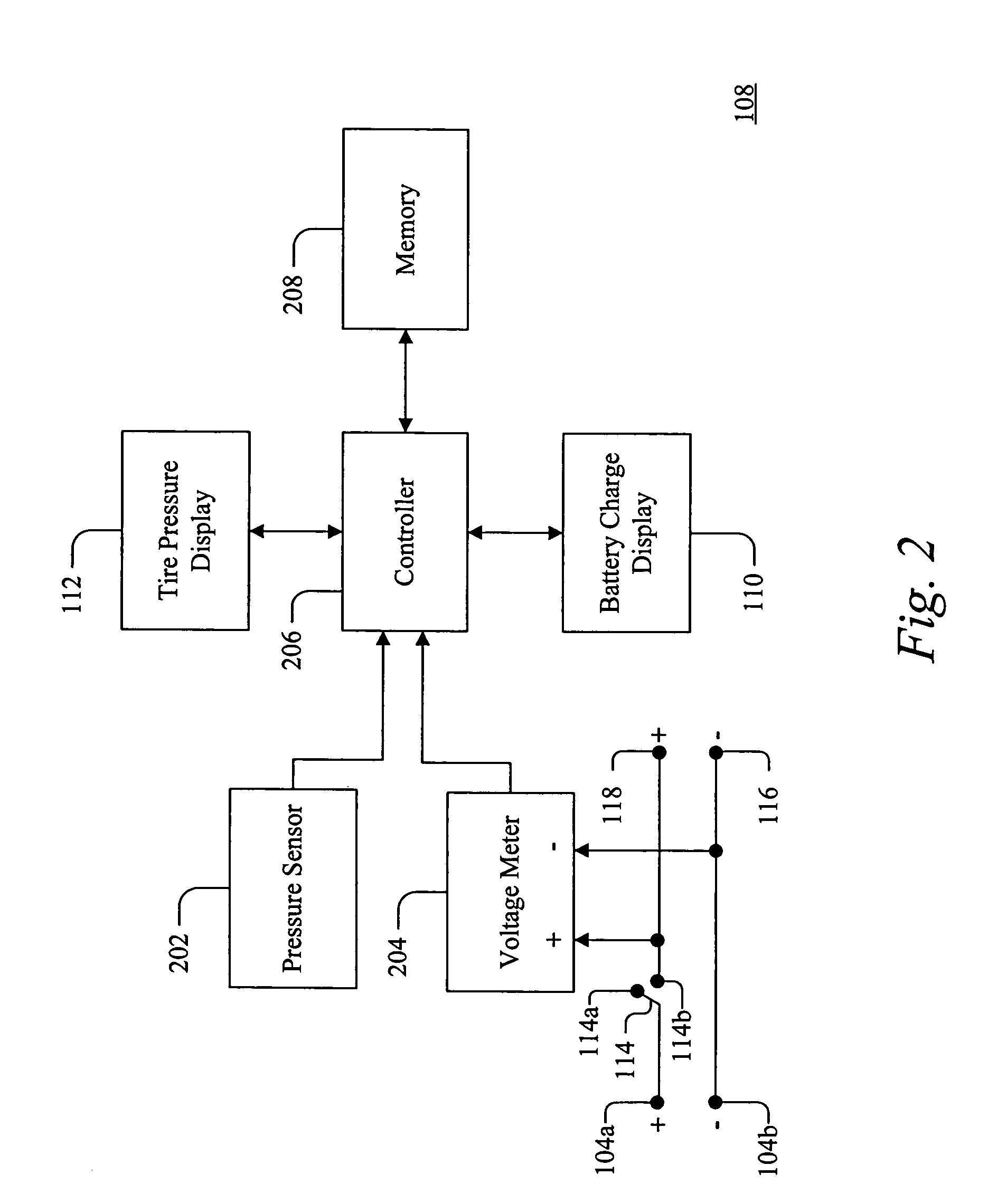
[0021]Referring to FIG. 1, a tire pressure sensor battery charging system 100 includes a charging device 108 that is coupled to an electric power source, such as an alternating current-direct current (AC-DC) converter 104. In one embodiment, the AC-DC converter 104 receives an AC input from an AC power source 106 by a power line 106a, such as an 110-volt wall socket, and converts the AC i...


PUM


Abstract

A device and method for extending the lifetime of a battery of a tire pressure sensor disposed in a tire are described, in which the battery can be recharged through the valve stem of the tire. The device includes an electrical power source and an electrode adapted to be coupled to the valve stem and supply power from the electrical power source to the valve stem.

Description

[0001]The present application is a divisional of U.S. patent application Ser. No. 10 / 141,136 filed on May 9, 2002 now U.S. Pat. No. 6,693,547, the contents of which are hereby incorporated by reference.FIELD OF THE INVENTION[0002]The present invention generally relates to tire pressure sensors and more particularly to extending the lifetime of a battery of a tire pressure sensor disposed in a tire.DISCUSSION OF THE BACKGROUND[0003]Various types of tire pressure sensors have been developed that are situated within tires of vehicles (see, e.g., U.S. Pat. Nos. 5,540,092 and 5,987,980). These tire pressure sensors require electrical power to monitor and transmit information regarding the current tire pressure for display in the passenger compartment of the vehicle. Typically, the tire pressure sensors are powered by long-life batteries also disposed within the tires. The lifetime of these long-life batteries, however, is five to ten years, which is less than the life span of many automo...

Claims


Application Information

Patent Timeline
Patent Type & Authority Patents(United States)
IPC IPC(8): G08B21/00B60C23/04
CPCB60C23/0408B60C23/041
Inventor MANAKKAL, RAJ
Owner HONDA MOTOR CO LTD
Learn More