Cutting insert and cutting tool

a cutting tool and cutting insert technology, applied in the direction of cutting inserts, manufacturing tools, shaping cutters, etc., to achieve the effects of overcoming or reducing deficiencies, reducing the number of cutting tools, and improving clamping

Active Publication Date: 2013-09-10
ISCAR LTD
View PDF11 Cites 9 Cited by
  • Summary
  • Abstract
  • Description
  • Claims
  • Application Information

AI Technical Summary

Benefits of technology

[0016]The inclination of the support sections secures the insert to the insert holder firmly and allows better clamping. The pocket of the tool for receiving said inserts has rounded recesses for accommodating the corners of the insert to allow a proper seat of the insert in the pocket.
[0017]The present invention has the preferred advantage over the prior art that a cutting insert as well as a tool holder for such inserts is provided which overcome or reduce deficiencies of the prior art and preferably have advantages as to durability, service life or life time, accuracy, effectiveness and efficiency. Even preferably the preciseness of a cutting process can be increased by providing a more precise and longer lasting secure and reproducible position of the major cutting edge of the cutting insert in a tool holder and by preferably alternatively or more preferably additionally improving resistance to forces applied to the cutting insert or the tool holder, e.g. during a cutting operation. Further or additional preferred advantages of the present invention are obvious from the general discussion above as well as the detailed discussion of preferred embodiments as provided below. In particular, the cutting insert of the present invention allows the provision of four indexable major cutting edges thereby improving lifetime and effectiveness of the insert. Also, by provision of an additionally abutment surface, better clamping and positioning of the insert becomes possible. This preferably allows the insert to be used for tougher cutting conditions. Furthermore, the third support or abutment section in the discussed orientation to the other section preferably allows the insert to rotate to its final position in the insert holder while maintaining a contact with both support sections at the same time. Moreover, the transition surface allows a deeper cut.

Problems solved by technology

The major non-cutting edges defined between the top or bottom surface and the relief surface which do not constitute cutting edges, do not smoothly merge with the respective transition cutting edge provided between the transition surface and the respective top or bottom surface of the insert since these major non-cutting edges are not tangent to the transition surface.

Method used


Image

  • Cutting insert and cutting tool
  • Cutting insert and cutting tool
  • Cutting insert and cutting tool

Examples


Embodiment Construction

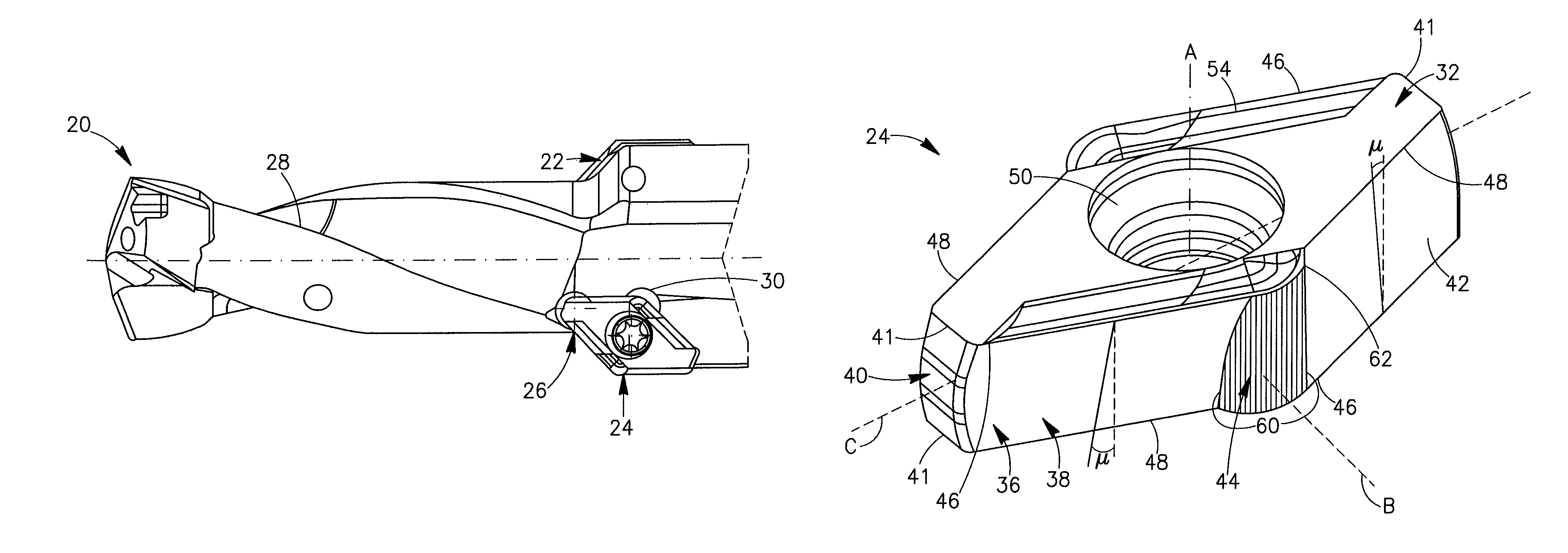
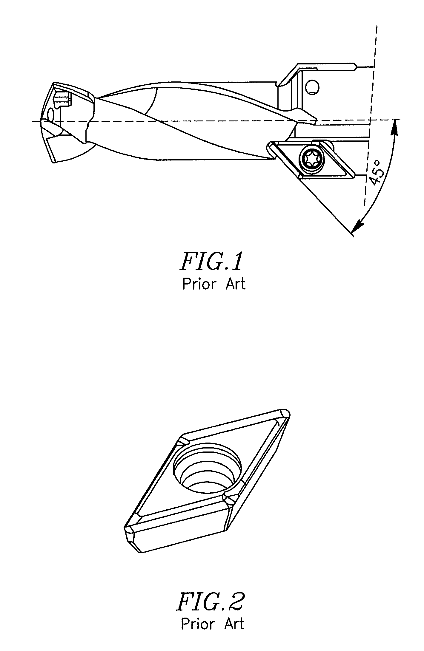
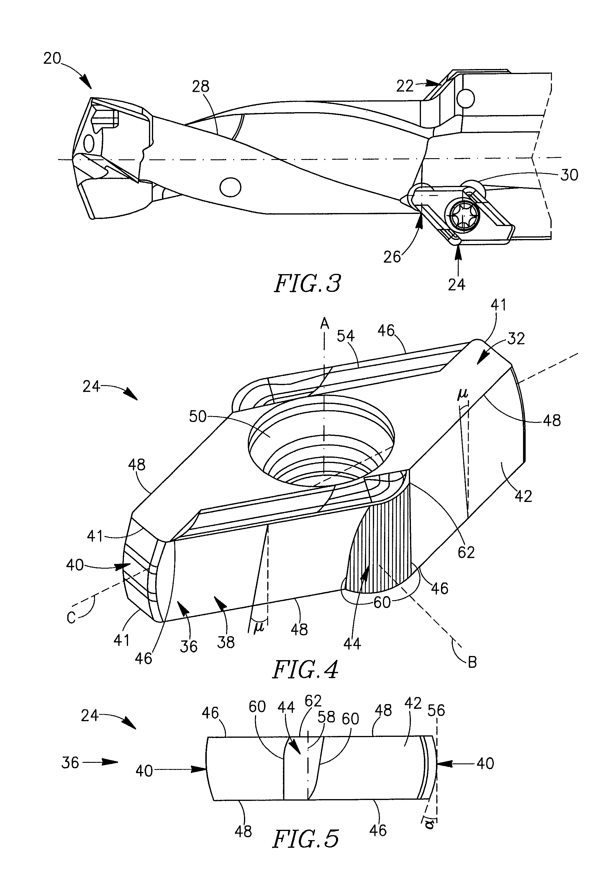
[0034]Attention is first drawn to FIG. 3 showing a cutting tool 20 in accordance with the present invention. The cutting tool 20 may be used for metal cutting operations such as chamfering and counterboring or countersinking for drills or milling cutters. The cutting tool 20 has an insert holder 22 with a double-sided cutting insert 24 retained in an insert pocket 26 and flutes 28 for chip evacuation. The insert pocket 26 has rounded recesses 30 to accommodate corners of the insert 24.

[0035]FIG. 4 shows the cutting insert 24 from a perspective top view. The cutting insert 24 has unitary one-piece construction with a generally rhomboidal body and has two identical opposed top and bottom surfaces 32, 34 and a peripheral side surface 36 extending between the top and bottom surfaces 32, 34. The distinction between the top and bottom surfaces 32, 34 does not restrict the discussed insert, particularly the discussed indexable insert, to a particular orientation, but merely serves to clear...


PUM

PropertyMeasurementUnit
convergent angleaaaaaaaaaa
clearance angleaaaaaaaaaa

Abstract

A double-sided cutting insert has top and bottom surfaces and two major side surfaces connected by two minor side surfaces. Each major side surface has two distinct relief surfaces which are inclined in opposite directions and merge at a transition surface extending between top and bottom surfaces. A first major cutting edge is defined between the first relief surface and the top surface and a second major cutting edge is defined between the second relief surface and the bottom surface. Each major cutting edge is tangent to an associated transition cutting edge defined between the transition surface and the insert top or insert bottom surface. An insert holder for the insert has three support sections accordant with three abutment sections of the insert.

Description

FIELD OF THE INVENTION[0001]The present invention is directed to a cutting insert and a cutting tool for such an insert. The invention is particularly directed to a chamfering and counterboring or countersinking insert for drills or milling cutters.BACKGROUND OF THE INVENTION[0002]In the art, single-sided cutting inserts for cutting metal and particularly chamfering and counterboring insert for drills and respective tools are known. For example, referring to FIG. 1, there is shown a drill with two such inserts. Each insert is generally rhomboidal having opposing top and bottom surfaces and a peripheral side surface extending between the top and bottom surfaces. The peripheral side surface comprises two major side surfaces of which each has two major side surface sections of which only one defines a cutting edge with the top surface. Each two major side surface sections meet at a transition edge. The cutting insert has a 180° rotational symmetry about a first axis extending through t...

Claims


Application Information

Patent Timeline
Patent Type & Authority Patents(United States)
IPC IPC(8): B32B27/02B23B27/22
CPCB23B51/108B23B27/1614B23B2251/50Y10T407/23B23B2205/12B23B2200/086B23B2200/123Y10T407/2274Y10T407/235B23B51/0003
Inventor SHAHEEN, PHILIP
Owner ISCAR LTD
Why Eureka
Try Eureka