Pendular joint decompression device

a decompression device and pendular joint technology, applied in the field of joint decompression, can solve the problems of not allowing the person's legs to flex, the device does not allow for reproducing movement close,

Pending Publication Date: 2021-09-02
SATISFORM
View PDF0 Cites 1 Cited by
  • Summary
  • Abstract
  • Description
  • Claims
  • Application Information

AI Technical Summary

Benefits of technology

[0051]Thus, the foam or gel provides comfort to the user during operation of the pendular joint decompression device....

Problems solved by technology

However, this existing device does not allow for reproducing movement close to walking on the perso...

Method used


Image

  • Pendular joint decompression device
  • Pendular joint decompression device
  • Pendular joint decompression device

Examples


first embodiment

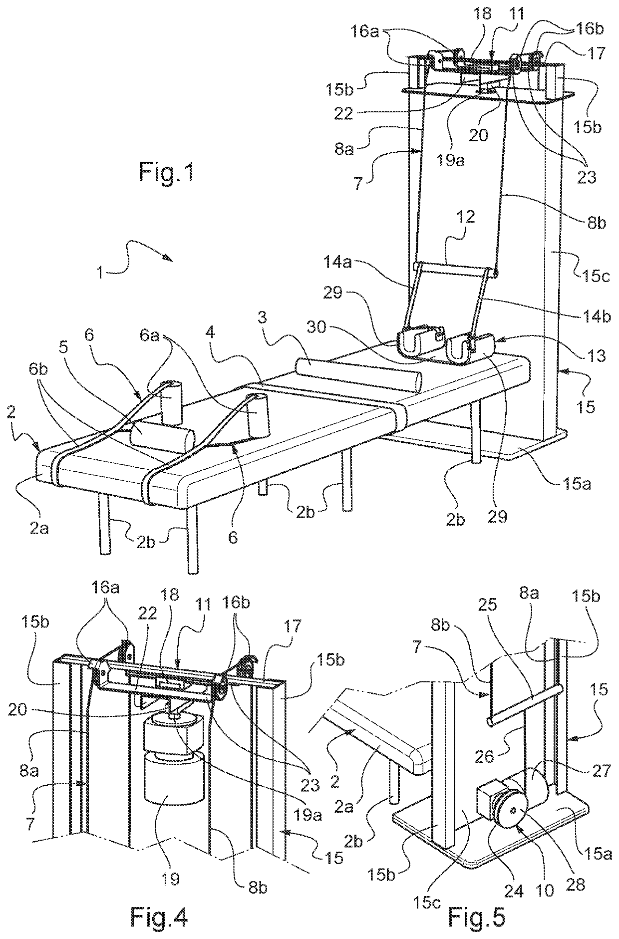
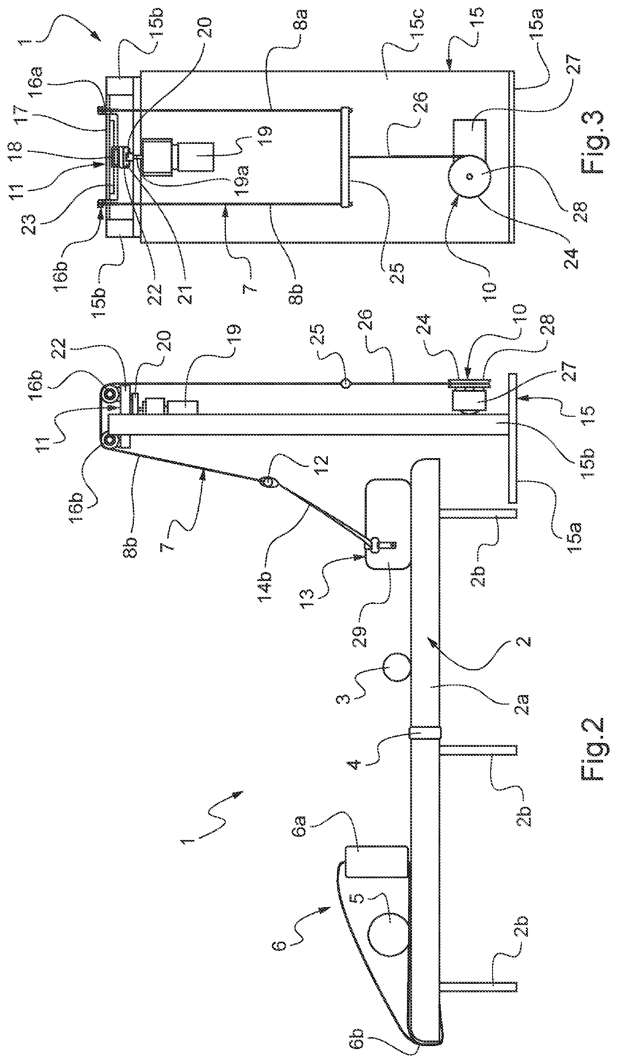
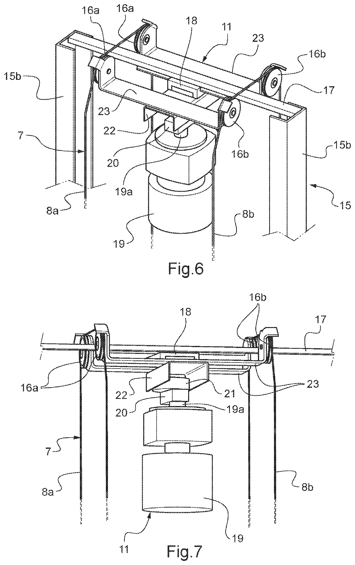
[0074]Referring to FIGS. 1 to 5, it can be seen that a pendular joint decompression device 1 according to the present invention is shown there.

[0075]The pendular joint decompression device 1 comprises a table 2 configured to support a person lying on his or her back, the table 2 comprising a horizontal top 2a, equipped with a mattress, raised by vertical legs 2b.

[0076]The table 2 further comprises a horizontal transverse cushion 3 that defines a support surface for the person's knees, a belt 4 for blocking the person's waist, a cushion 5 that defines a support surface for the person's head, and two armpit blocking systems 6 that allow the person to be held lying by the armpits. Each armpit blocking system 6 comprises a vertical coil 6a intended to be placed under one of the person's armpits, the vertical coil 6a being connected to a strap 6b, whose two ends are attached under the horizontal top 2a of the table 2.

[0077]Thus, the various elements 3, 4, 5, 6 mentioned above allow for ...

second embodiment

[0135]Referring to FIG. 11, a leg-receiving means 113 according to a first variant of the present invention can be seen.

[0136]The leg-receiving means 113 according to the first variant of the second embodiment comprises two chutes 129 connected in parallel to each other, each chute 129 being adapted to receive one of the legs 40 of the person.

[0137]Each chute 129 comprises fastening means 129a (e.g., of the ski boot fastening or hook and loop type or such like) for closing the chute 129 after the leg is placed therein.

[0138]The leg-receiving means 113 further comprises a counter bearing bar 170 positioned perpendicular to the chutes 129 and attached above the chutes 129 at the foot-side ends thereof. The counter bearing bar 170 has a relatively large diameter, preferably between 3 centimeters and 20 centimeters.

[0139]The two cables 8a and 8b are directly connected to the counter-bearing bar 170.

[0140]The application points of the two cables 8a and 8b to the counter-bearing bar 170 a...


PUM


Abstract

A pendular joint decompression device including a table configured to support a person lying on his or her back, and a traction system including cabling, a leg-receiving unit secured to the cabling and configured to link this cabling to the person's legs, a traction unit configured to act on the cabling, an oscillator configured to act on the cabling, and a control unit capable of controlling the traction unit and the oscillator in order to combine lateral oscillation movements and traction movements on the person's raised legs, characterized by the fact that the leg-receiving unit is configured to apply, for each of the person's legs, a force on the rear of the calf and a force on the front of the ankle, simultaneously, when the traction unit acts on the cabling.

Description

CROSS-REFERENCE TO RELATED APPLICATIONS[0001]This application is the U.S. national phase of International Application No. PCT / IB2019 / 059693 filed Nov. 12, 2019 which designated the U.S. and claims priority to FR 1871526 filed Nov. 14, 2018, the entire contents of each of which are hereby incorporated by reference.BACKGROUND OF THE INVENTIONField of the Invention[0002]The present invention relates to the field of joint decompression, and, in particular, to a pendular joint decompression device.[0003]Pendular joint decompression consists of decompression by neuromuscular relaxation generated by pendular movement, particularly for the ankles, knees, hips, pelvis and spine, by traction and oscillation of the legs of a person. In addition to joint decompression of the spine, pelvis, hips, knees and ankles, pendular joint decompression strengthens the deep muscles for a lasting effect. Pendular joint decompression is used in particular in the therapeutic and preventive fields and to impro...

Claims


Application Information

Patent Timeline
IPC IPC(8): A61H1/02
CPCA61H1/0222A61H1/0237A61H2201/149A61H2201/1215A61H2201/1621A61H2201/1642A61H2201/1418A61H1/02A61H2001/0251A61H2205/08A61H2205/10A61H2203/0456A61H2201/5002A61H1/0218A61H1/0292A61H2201/1616
Inventor BENSOUSSAN, CHRISTOPHE
Owner SATISFORM
Why Eureka
Try Eureka