
Apparatus for forming a protecting duct with integrated inner and outer walls, and the duct formed thereby

Pending Publication Date: 2021-09-09
ITECO LTD
View PDF0 Cites 0 Cited by
  • Summary
  • Abstract
  • Description
  • Claims
  • Application Information

AI Technical Summary

Benefits of technology

This invention has the following benefits: 1. The design has a smooth duct and a corrugated duct that increases compressive strength. 2. The design allows for precise shaping and sizing of the inner and outer walls, improving the dimensional accuracy of both walls. 3. The design has a coolant flow path formed inside the inner-wall dice and inner-wall sizing machine, improving cooling efficiency compared to conventional apparatus. 4. The design is simpler and less expensive to manufacture and operate than conventional apparatus. 5. The resulting protection duct has no seam and can be coiled up to a length of 500 meters to 1000 meters and thus can be laid at once without using connecting members to link a large number of ducts.

Problems solved by technology

This lowers cooling efficiency, and more time is required for cooling, delaying the whole manufacturing process.
In the apparatus of the Document 2 the pressing member, which brings the inner wall in close contact with the outer wall, drives a pressing roll using a power transmission element, and this structure increases manufacturing and operating costs of the apparatus as well as complexity.
In addition, while the outer wall is shaped spirally by a vacuum adsorption, the dimensions of the inner wall are not precisely controlled because there is no configuration for shaping the inner wall and the inner surface of the inner wall is pushed outward to be in close contact with the outer wall.
Meanwhile, previous apparatuses for forming protection ducts were not able to integrate the inner wall with the outer wall tightly, which lowered the compression strength of the formed duct.
Furthermore, insufficient integration of the inner and outer walls made coiling of the duct difficult so that the protection duct was formed into a short length (for example, 6 meters) and then connected using an additional connecting accessory.

Method used


Image

  • Apparatus for forming a protecting duct with integrated inner and outer walls, and the duct formed thereby
  • Apparatus for forming a protecting duct with integrated inner and outer walls, and the duct formed thereby
  • Apparatus for forming a protecting duct with integrated inner and outer walls, and the duct formed thereby

Examples


Embodiment Construction

[0029]Hereinafter, preferred embodiments of the present invention will be described in detail with reference to the accompanying drawings. However, the present invention may be modified in various different forms without being limited to the embodiments described below. The embodiments of the present invention are provided to help those skilled in the field to fully understand the invention.

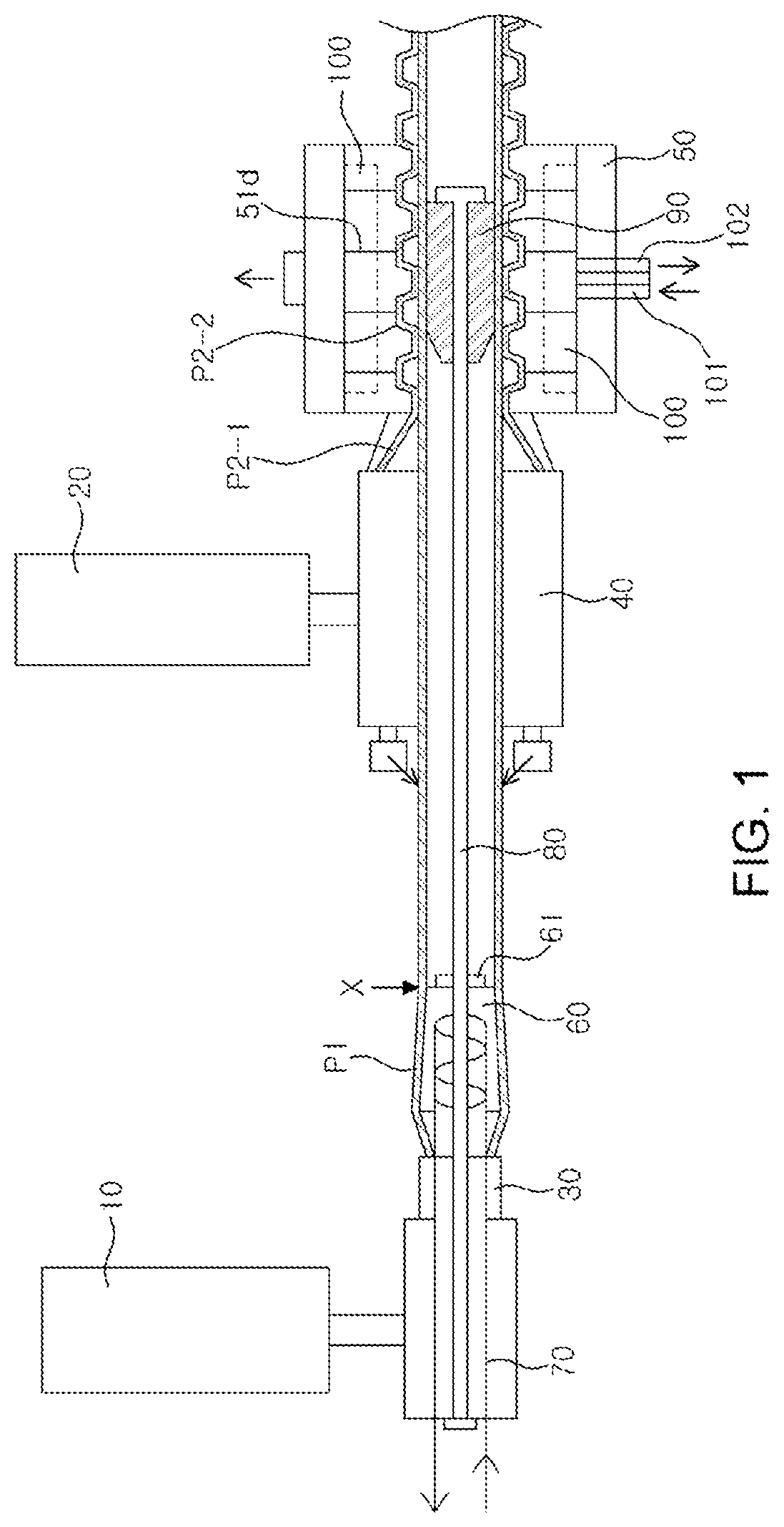
[0030]FIG. 1 shows the structure of the apparatus for forming a protecting duct with the integrated inner / outer walls. As shown in FIG. 1, the apparatus of the present invention includes an inner-wall resin extruder 10 for extruding the inner-wall molding resin and an outer-wall resin extruder 20 for extruding the outer-wall molding resin.

[0031]The inner-wall molding resin, extruded from the inner-wall resin extruder 10, is semi-solid resin and supplied to the inner-wall dice 30 for molding of the inner wall P1. The outer-wall molding resin, extruded from the outer-wall resin extruder 20, is also...


PUM

PropertyMeasurementUnit
Angleaaaaaaaaaa

Abstract

According to an embodiment of the present disclosure, a cylindrical sizing machine is located next to the inner-wall dice, which reduces the outer diameter of the inner wall to a desired length as it passes from the entry point into which the semi-solid inner wall is introduced to the end point; a coolant flow path, through which the coolant is supplied from an external source, is formed within the inner-wall dice and the inner-wall sizing machine; a guide support rod is installed, extending from the inner-wall dice to the inside of the outer-wall sizing machine; an inner-wall guide supported by the guide support rod is installed in the outer-wall sizing machine at the position where the shaping occurs: and the semi-solid inner wall passes between the inner-wall guide and the outer wall being shaped for tight integration with the outer wall by means of pressurization.

Description

TECHNICAL FIELD[0001]The present invention relates to an apparatus for forming a protecting duct that is used to protect communication cables or power cables installed underground. In particular, the apparatus can manufacture a protecting duct with integrated inner and outer walls, which improves the forming speed and allows easy coiling while maintaining increased compressive strength.BACKGROUND ART[0002]Various communication cables such as telephone cables and optical fiber cables, as well as power cables, are often buried underground due to consideration for urban landscape. When communication / power cables are installed underground, a protecting duct, w % here the cables are inserted, is used to protect them from harmful insects or flood damage.[0003]Document 1 (Korea Patent No. 10-1454893) describes an apparatus for manufacturing an optical cable duct. In this apparatus, the 1st dice and the 2nd dice for extrusion molding of the inner and outer walls are located on both sides of...

Claims


Application Information

Patent Timeline
IPC IPC(8): B29C48/09B29C48/13
CPCB29C48/09B29L2023/186B29C48/13B29C48/21B29C48/902B29C48/903B29L2023/22B29C48/0016B29C48/9115B29C48/0017B29C48/151B29C48/32B29C48/34B29C48/885B29C48/908B29C48/916H02G3/0468F16L9/18B29D23/00F16L9/06B29C48/18B29C48/901B29C48/25
Inventor LEE, KYUNG RO
Owner ITECO LTD
Learn More