Microcellular polymer foams and method for their production

Inactive Publication Date: 2001-05-15
TAN SENG C
View PDF5 Cites 80 Cited by
  • Summary
  • Abstract
  • Description
  • Claims
  • Application Information

AI Technical Summary

Benefits of technology

Because of the high compressive strengths demonstrated by the foams and composites of the present invention, they are particularly useful in composite structures of the type which utilize a foamed polymer as the core of a metal, or otherwise skinned laminate. A l

Problems solved by technology
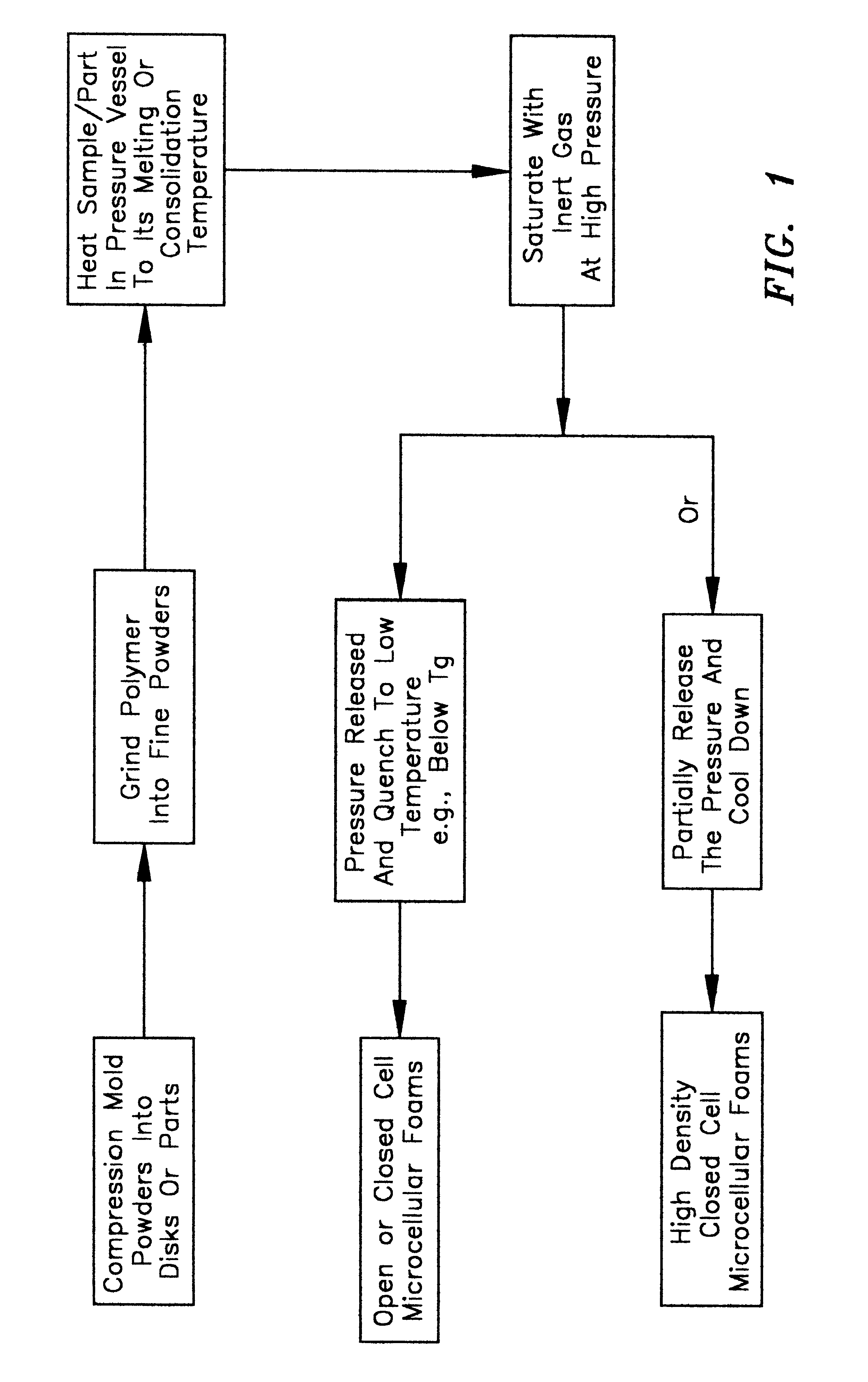
Most commercial foam production processes involve the use of chemical blowing agents (CBAs) which decompose during processing or blowing gases like CFCs or carbon monoxide, which are toxic or polluting.
Such foaming techniques generally produce foams whose cell sizes are on the order of millimeters and have mechanical properties much weaker than those of the solid form of the parent polymer material.
The production of such foams poses several

Method used


Image

  • Microcellular polymer foams and method for their production

Examples


example 1

Samples of Xydar SRT-900, a liquid crystal polymer available for Amoco Chemical Corp. 4500 McGinnis Rd., Alpharettat, Ga. 30202, a powder, were compression molded into a discs 2.26" in diameter and 0.12" at about 1000 psi. Saturation was performed in the same pressure vessel / die combination as consolidation with nitrogen gas at a pressure of 3000 to 4200 psi, a temperature of from about 380 to about 400.degree. C. and for a period for 20 to 50 minutes. Quenching was accomplished by injecting compressed air into the vessel. The resulting foams had the structure shown in the SEM of FIG. 2. After foaming, the samples had expanded to a thickness of 0.42" while the diameter remained essentially the same due to the constraints of the die in which the foaming was performed. The stress-strain capabilities of one of these samples are shown as curve 1 in FIG. 3. Mounting of a sample on an adhesive block followed by polishing with 220 grit sandpaper and diamond based polishing compounds, accor...

example 2

Chopped glass fibers identified as 165A11C obtained from Owens Corning, One Owens Corning Parkway, Toledo, Ohio 43659 were blended with Xydar SRT-900 using a blender. Material blends of approximately 15 and 30% fiber by weight were prepared. The polymer blends were then compression molded in a die as described above to form discs approximately 2.256" in diameter and about 0.15" thick. The glass filled polymer discs were then foamed as described in Example 1 above. One 15% loaded disc swelled to about 0.39", a second 15% loaded disc swelled to 0.40", and the 30% loaded disc swelled to 0.19" after foaming. The structure of samples of 15% loaded material is shown in the SEM of FIG. 5 and a 30% loaded material is shown in FIG. 6.

The compression strain relationships of these materials are shown as samples 2 (15% loaded), 3 also 15% loaded but compression formed twice instead of once as with sample 2, and 4 (30% loaded) in FIG. 3. It should be noted that the reinforcing fibers are aligned...

example 3

Polyphenylene sulfide supplied by Hoechst-Celanese, 90 Morris Ave., Summit, N.J. 07901, as Fortron.RTM. 0205B4 available as a fine powder was compression molded into discs about 2.25" in diameter and 0.16" thick by subjecting them to a pressure of 12,000 psi. Saturation of the compression molded discs was performed at a temperature of from about 300 to about 350.degree. C., and a pressure of 3500 psi for a period of from about 20 to about 40 minutes under a nitrogen atmosphere. The bubble sizes ranged from about 30 to about 120 .mu.m in diameter. The compression load deformation relationship of these materials shows that this material fails at 13.4% average strain while the solid counterparts of this material fails at 3-6%. The compression strength of these foams is 1945 psi, 1190 psi and 824 psi along the x, y, and z axes, respectively.

30% chopped glass loaded samples of Fortron.RTM. were prepared in the same fashion as just described for the unfilled foams, except that glass fiber...


PUM

PropertyMeasurementUnit
Percent by massaaaaaaaaaa
Pressureaaaaaaaaaa
Pressureaaaaaaaaaa

Abstract

An environmentally friendly, commercially practicable process for the production of microcellular polymer foams from amorphous, semi-crystalline and crystalline polymers that comprises consolidating the polymer into a polymer shape, saturating the polymer shape with an inert gas at elevated temperature, above the Tg of the polymer, and under elevated pressure, releasing the pressure and cooling, i.e. quenching, the saturated polymer polymer shape under controlled temperature and pressure conditions to produce either a closed or open celled, low to medium density microcellular foam or a closed cell, high density microcellular foam.

Description

The present invention relates to microcellular polymer foams and methods for their production and more specifically to microcellular crystalline and semi-crystalline polymer foams produced by a similar method. Filled polymer foams and methods for their manufacture are also described.The production of polymeric foams is well known in the art. For example, foams of amorphous polymers such as polystyrene have been manufactured for decades. Most commercial foam production processes involve the use of chemical blowing agents (CBAs) which decompose during processing or blowing gases like CFCs or carbon monoxide, which are toxic or polluting. Such foaming techniques generally produce foams whose cell sizes are on the order of millimeters and have mechanical properties much weaker than those of the solid form of the parent polymer material.Structural foams have more recently been processed from polymers such as polymethacrylic imide and polyvinyl urea-amides. The production of such foams po...

Claims


Application Information

Patent Timeline
IPC IPC(8): B29C44/34C08J9/00C08J9/18
CPCB29C44/3446B29C44/3453B29C44/348C08J9/18C08J2201/032
Inventor TAN, SENG C.
Owner TAN SENG C
Why Eureka
Try Eureka