Encoding device and encoding method

Active Publication Date: 2021-09-09
PANASONIC INTELLECTUAL PROPERTY CORP OF AMERICA
View PDF0 Cites 0 Cited by
  • Summary
  • Abstract
  • Description
  • Claims
  • Application Information

AI Technical Summary

Benefits of technology

The patent text describes how to efficiently encode an S signal in MS predictive encoding. The technical effect is that this allows for effective and efficient encoding of the S signal in this way.

Problems solved by technology

However, a method for efficiently encoding the S signal in the MS predictive encoding has not been comprehensively studied.

Method used


Image

  • Encoding device and encoding method
  • Encoding device and encoding method
  • Encoding device and encoding method

Examples


embodiment 1

[0029][Overview of Communication System]

[0030]A communication system according to the present embodiment includes encoder 100 and decoder 200.

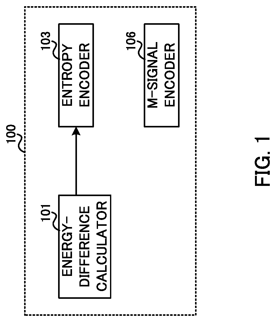
[0031]FIG. 1 is a block diagram illustrating a configuration example of a part of encoder 100 according to the present embodiment. In encoder 100 illustrated in FIG. 1, M-signal encoder 106 encodes a sum signal indicating the sum of a left channel signal and a right channel signal constituting a stereo signal, so as to generate first encoding information.

[0032]Energy-difference calculator 101 calculates a prediction parameter for predicting a difference signal indicating a difference between the left channel signal and the right channel signal using a parameter relating to an energy difference between the left channel signal and the right channel signal. Entropy encoder 103 encodes the prediction parameter to generate second encoding information.

[0033][Configuration of Encoder]

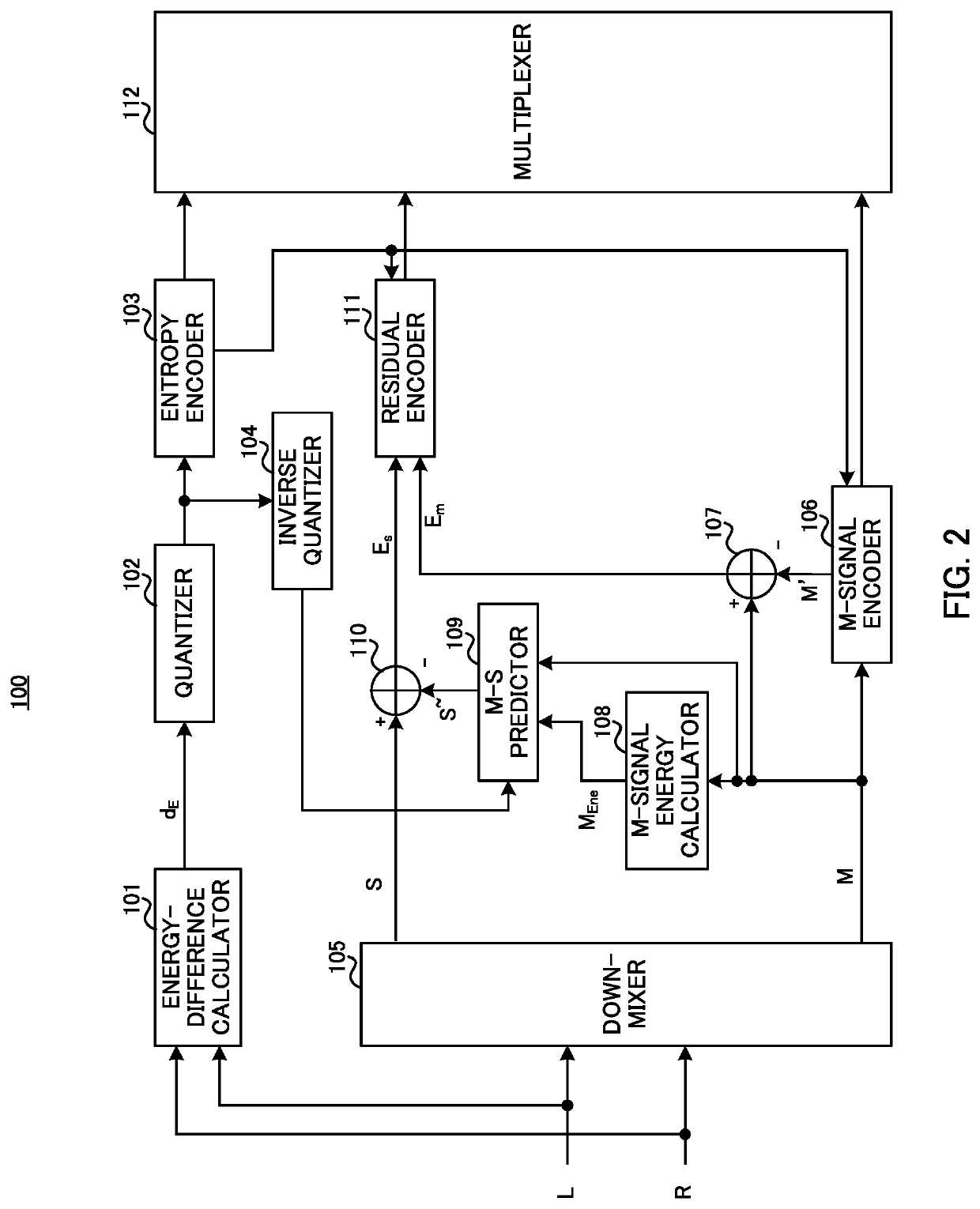
[0034]FIG. 2 is a block diagram illustrating a configuration exampl...

embodiment 2

[0083]Embodiment 1 has been described in which the prediction parameter used for calculating the prediction S signal is calculated using the energy difference between the L signal and the R signal of the stereo signal. Unlike such an embodiment, the present embodiment will be described in which the prediction parameter used for calculating the prediction S signal is calculated using the M signal and S signal.

[0084][Configuration of Encoder]

[0085]FIG. 4 is a block diagram illustrating a configuration example of encoder 300 according to the present embodiment. Note that, the same components between FIG. 4 and Embodiment 1 (FIG. 2) are provided with the same reference symbols, and descriptions of such components are omitted.

[0086]Prediction-coefficient calculator 301 calculates an M-S prediction coefficient using an S signal inputted from down-mixer 105 and a decoded M signal inputted from M-signal encoder 106. Prediction-coefficient calculator 301 outputs the calculated M-S prediction...

embodiment 3

[0114]Embodiments 1 and 2 have been described in which prediction of the S signal is performed using the M signal in predictive encoding. In contrast, the present embodiment will be described in which prediction of the L signal and the R signal is performed using the M signal in the predictive encoding. In other words, in the present embodiment, neither an encoder nor a decoder perform prediction of the S signal.

[0115][Overview of Communication System]

[0116]A communication system according to the present embodiment includes encoder 500 and decoder 600.

[0117][Configuration of Encoder]

[0118]FIG. 6 is a block diagram illustrating a configuration example of encoder 500 according to the present embodiment. In FIG. 6, encoder 500 includes down-mixer 501, M-signal encoder 502, prediction-coefficient calculator 503, quantization encoder 504, inverse quantizer 505, channel predictor 506, residual calculator 507, residual encoder 508, and multiplexer 509.

[0119]FIG. 6 illustrates that an L sig...


PUM


Abstract

This encoding device is able to encode an S signal efficiently in MS prediction encoding. An M signal encoding unit generates first encoding information by encoding a sum signal indicating a sum of a left channel signal and a right channel signal that constitute a stereo signal. An energy difference calculation unit calculates a prediction parameter for predicting a difference signal indicating a difference between the left channel signal and the right channel signal by using a parameter regarding an energy difference between the left channel signal and the right channel signal. An entropy encoding unit generates second encoding information by encoding the prediction parameter.

Description

TECHNICAL FIELD[0001]The present disclosure relates to an encoder and an encoding method.BACKGROUND ART[0002]A Middle / Side (M / S) stereo codec converts signals of channels (left channel and right channel) constituting a stereo signal into an M signal (also called sum signal) and an S signal (also called difference signal), and encodes the M signal and S signal by a mono speech audio codec. In addition, an encoding method for the M / S stereo codec to predict the S signal using the M signal (hereinafter referred to as MS predictive encoding) has been proposed (see, for example, Patent Literatures (hereinafter referred to as “PTLs”) 1 to 3).CITATION LISTPatent LiteraturePTL 1[0003]Japanese Patent No. 5122681PTL 2[0004]Japanese Unexamined Patent Application Publication (Translation of PCT Application) No. 2014-516425PTL 3[0005]Japanese Patent No. 5705964Non-Patent LiteratureNon-Patent Literature 1[0006]Recommendation ITU-T G.719 (June 2008), “Low-complexity, full-band audio encoding for h...

Claims


Application Information

Patent Timeline
IPC IPC(8): G10L19/04G10L19/008G10L19/02
CPCG10L19/04G10L19/0212G10L19/008G10L25/12
Inventor NAGISETTY, SRIKANTHEHARA, HIROYUKIMARS, ROHITHLIM, CHONG SOONSAKURAI, TOSHIAKI
Owner PANASONIC INTELLECTUAL PROPERTY CORP OF AMERICA
Why Eureka
Try Eureka