Battery pack

Pending Publication Date: 2021-09-09
HONDA MOTOR CO LTD
View PDF7 Cites 0 Cited by
  • Summary
  • Abstract
  • Description
  • Claims
  • Application Information

AI Technical Summary

Benefits of technology

[0005]However, when a complicated structure is adopted to prevent water from entering from a gas discharge unit

Problems solved by technology

However, when a complicated structure is adopted to prevent water from entering from a gas discharge unit su

Method used


Image

  • Battery pack
  • Battery pack
  • Battery pack

Examples


Example

[0024]Hereinafter, an embodiment of a battery pack of the present invention will be described with reference to the drawings. In the drawing, the front of a vehicle equipped with the battery pack is shown as Fr, the rear is shown as Rr, the left side is shown as L, the right side is shown as R, the upper side is shown as U, and the lower side is shown as D. However, a mounting posture of the battery pack is not limited to this.

[0025]Vehicle

[0026]First, an example of a vehicle equipped with a battery pack of the embodiment will be described.

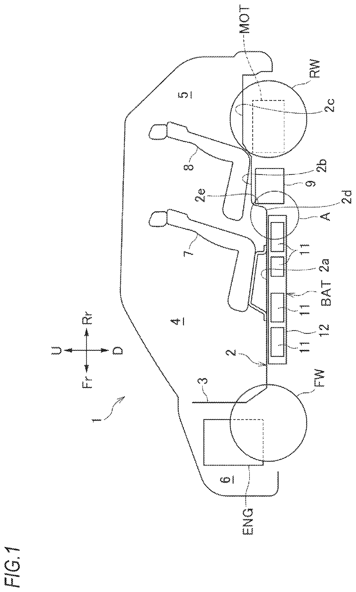
[0027]As illustrated in FIG. 1, a vehicle 1 is divided into a passenger compartment 4, a luggage compartment 5, and a front room 6 in front of them by a floor panel 2 and a dash panel 3. The passenger compartment 4 is provided with a front seat 7 and a rear seat 8. The front room 6 is provided with an engine ENG as a drive source for driving left and right front wheels FW and an electric motor MOT as a drive source for driving left and right rear ...


PUM


Abstract

A battery pack which is placed below a floor panel of a vehicle, includes a battery, a case for accommodating the battery, and a pressure release mechanism for releasing pressure inside the case. The pressure release mechanism includes a communication member which has one end and the other end and where the one end is connected to the case, and a gas discharge unit connected to the other end of the communication member and having a labyrinth structure.

Description

CROSS-REFERENCE TO RELATED APPLICATION[0001]The present application claims the benefit of priority of Japanese Patent Application No. 2020-037275, filed on Mar. 4, 2020, the content of which is incorporated herein by reference.TECHNICAL FIELD[0002]The present invention relates to a battery pack mounted on a vehicle.BACKGROUND ART[0003]Each cell of a battery mounted inside a battery pack releases gas to the outside of the cell, that is, inside the battery pack, through a gas discharge valve when the pressure inside the cell increases. Generally, the battery pack has a closed structure, so when the pressure inside the battery pack increases, it is necessary to discharge gas to the outside of the batter pack.[0004]Therefore, in a recent year, a technique has been known in which a gas discharge valve is provided directly on a case of a battery pack or a gas discharge valve is provided via a hose. However, it is necessary to prevent water from entering the case of the battery pack from t...

Claims


Application Information

Patent Timeline
IPC IPC(8): H01M50/249B60K1/04B62D25/20B60K13/04B60K6/28H01M50/204H01M50/317H01M50/358
CPCH01M50/249B60K1/04B62D25/20B60K13/04B60K6/26H01M50/204H01M50/317H01M50/358B60K2001/0438B60K6/28H01M2220/20B60K15/03B60K15/073B60K2015/0638Y02E60/10H01M50/35H01M2200/20B60K6/24
Inventor SHIMAZAKI, ITSUKIFUJII, RYOOHKUMA, KANAEIIJIMA, TAKAAKITAKAI, TAKAHIROAZUMA, YOHEI
Owner HONDA MOTOR CO LTD
Why Eureka
Try Eureka