Electrical connector and method of making an electrical connector

a technology of electrical connectors and connectors, which is applied in the manufacture of contact member cases/bases, coupling device connections, coupling contact members, etc., can solve the problems of insufficient reliability, inability to ensure electrical contact, and known electrical connectors from the state of the art, so as to ensure the stability of the spring box. , the effect of ensuring the stability

Active Publication Date: 2021-09-09
LEAR CORP
View PDF0 Cites 1 Cited by
  • Summary
  • Abstract
  • Description
  • Claims
  • Application Information

AI Technical Summary

Benefits of technology

[0028]According to a further embodiment of the connector, it is also advantageous if it is provided that the spring box is produced from a sheet metal blank by bending, and that the end edges of the sheet metal blank that are adjacent to one another by bending are connected to one another by a form-fit and / or material-fit. Preferably, the adjacent end edges of the sheet metal blank are joined together by means of a dovetail joint and / or a welded joint. In this way, advantageous stability of the spring box is ensured.
[0029]In a further embodiment of the connector, it is provided that the spring box is fastened to the base body in a force-fitting and / or a form-fitting manner. The spring box has, for example, a cutout in each of two opposite side faces. Within each cutout, at least one, and preferably two, connecting wings are provided that are caulked for connection to the base body. The cutout allows the caulking to be carried out in a simple manner.

Problems solved by technology

The greatest challenge is to achieve an increase in vibration resistance without geometric changes to the existing plug connectors, housings, and interfaces.
Electrical connectors known from the state of the art have the disadvantage that they are damaged in the event of strong and / or permanently occurring vibrations, as a result of which electrical contacting can no longer be ensured or can no longer be ensured reliably enough.

Method used


Image

  • Electrical connector and method of making an electrical connector
  • Electrical connector and method of making an electrical connector
  • Electrical connector and method of making an electrical connector

Examples


first embodiment

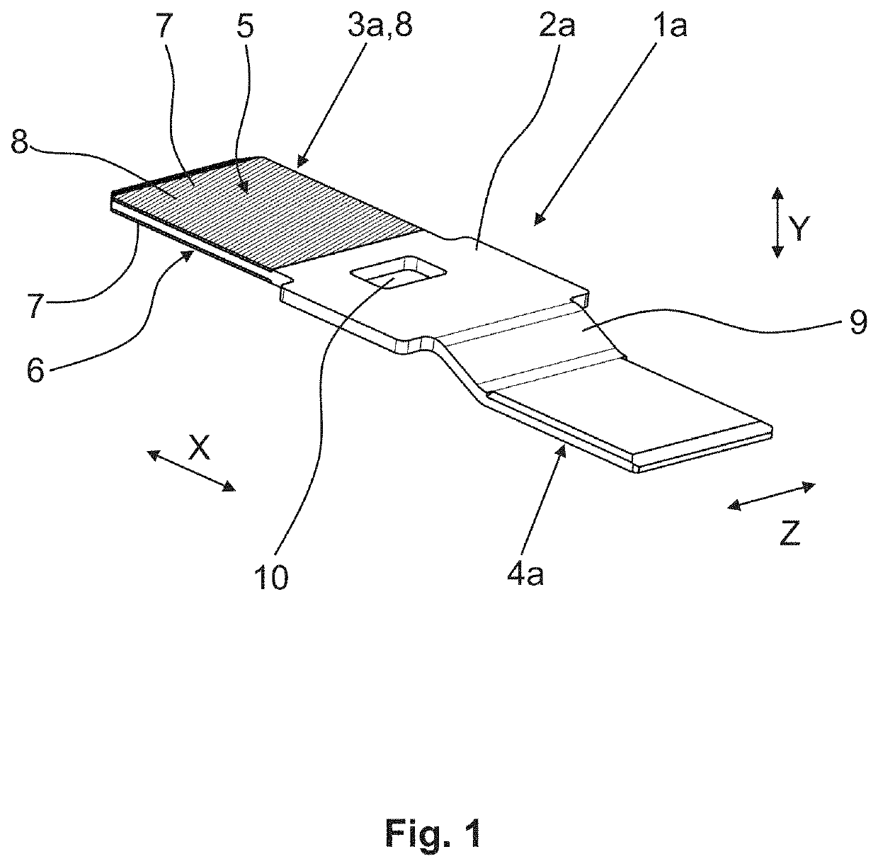
[0050]FIG. 1 shows an electrical connector 1a in a perspective view. The electrical connector 1a has a base body 2a with a contact portion 3a and a connection portion 4a. In the longitudinal direction of the connector 1a (i.e., in the direction of the double arrow X), the contact portion 3a and the connection portion 4a are disposed at opposite ends of the connector 1a. The contact portion 3a is provided for electrically contacting with at least one other connector (such as shown, for example, at 1b in FIGS. 2 and 3). The connection portion 4a is provided for fastening (such as, for example, by welding, soldering, or crimping) an electrical conductor (not shown). The base body 2 is made of a first material, such as copper. Both in a first surface area 5 of the contact portion 3a and in a second surface area 6 of the contact portion 3a, respectively, a layer 7 of the second material (such as, for example, an alloy of silver and nickel) is arranged.

[0051]In this first embodiment, the ...

second embodiment

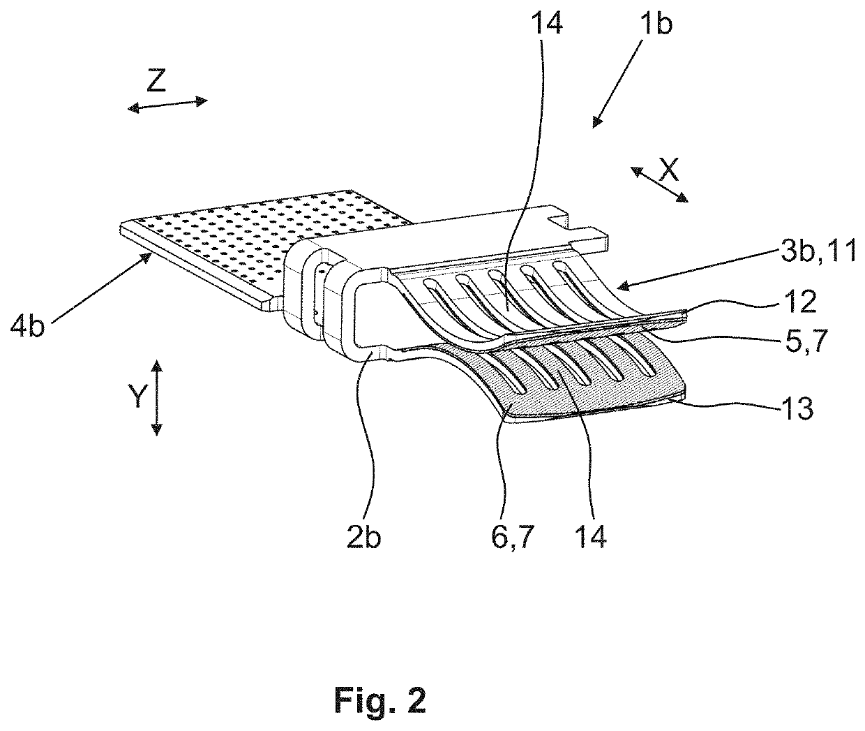
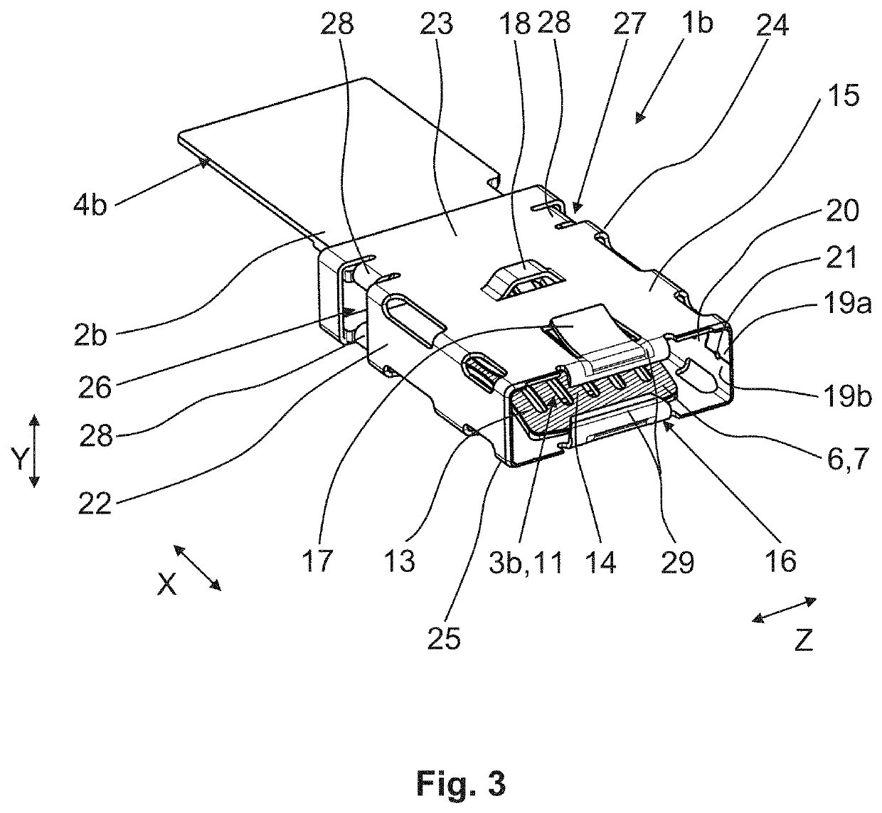
[0057]FIG. 3 shows the electrical connector 1b, whose base body 2b is formed with the contact portion 3b, the connection portion 4b, and the plug receptacle 11 according to the embodiment of FIG. 2, having a spring box 15 supported thereon.

[0058]Compared to the embodiment of FIG. 2, the plug receptacle 11 according to FIG. 3 is surrounded by the spring box 15 that defines an insertion opening 16 such as, for example, for the plug blade 8 according to the embodiment of FIG. 1. The spring box 15 further includes at least one resilient latching means 17 for securing the spring box 15 in a receptacle housing (not shown). In addition to the latching means 17, the spring box 15 also includes a secondary locking means 18 that is oriented transversely to the insertion direction, which is oriented along the double arrow X. The secondary locking means 18 is oriented in the Z direction and protrudes from the spring box 15 in the Y direction. The secondary locking means 18 and the latching mean...


PUM


Abstract

An electrical connector includes at least one base body with at least one contact portion and at least one connection portion. The connection portion is provided for fastening an electrical conductor. The base body is made of a first material, and a layer of a second material is arranged in a surface area of the contact portion. An electrical connector that ensures reliable electrical contacting even under heavy mechanical stresses is realized by applying the layer of the second material by means of roll cladding or an additive manufacturing process.

Description

BACKGROUND OF THE INVENTION[0001]The invention relates to an electrical connector and a method for manufacturing an electrical connector.[0002]A typical electrical connector has at least one base body with at least one contact portion and at least one connection portion. The contact portion is for establishing electrical contact with at least one further connector. The connection portion is provided for fastening at least one electrical conductor to the electrical connector, for example, by fastening the electrical conductor to the connection portion in a substance-to-substance manner. The base body is made of a first material. For example, the first material is a sheet of a metal. The base body has at least one layer of a second material in at least one surface region of the contact portion.[0003]In the prior art, it is known to provide the base body completely with a coating that is applied by galvanizing, for example. The application of the coating can serve, on the one hand, to ...

Claims


Application Information

Patent Timeline
Patent Type & Authority Applications(United States)
IPC IPC(8): H01R13/18H01R13/422H01R13/426H01R43/16H01R13/627
CPCH01R13/18H01R13/422H01R13/6271H01R43/16H01R13/426H01R13/629H01R13/17H01R43/18B33Y80/00H01R13/03
Inventor KLAWINSKI, ROBERTVESPER, SVENWEGER, MICHAELA
Owner LEAR CORP
Why Eureka
Try Eureka