Exercise equipment

a technology for exercise equipment and equipment, applied in the field of exercise equipment, can solve the problems of not being able to improve the movement of the wrist or ankle, the force of pinching the finger, and the inability of the exerciser to place his or her weight on the fingertips, so as to improve the movement of the scapula and the hip joint, and the effect of improving the arch of the foo

Active Publication Date: 2021-09-16
OZEKI TAKASHI
View PDF25 Cites 0 Cited by
  • Summary
  • Abstract
  • Description
  • Claims
  • Application Information

AI Technical Summary

Benefits of technology

[0017]According to the first aspect of the present invention, the exercise equipment of the present invention is provided with the pressing member made of a hard material, and the string and the connecting member are made of a non-stretchable material. The exerciser can use the pinching force, bending force, and warping force of the fingers and feet. By moving the wrists or ankles, it is possible to do a whole-body exercise linked from the spine even in a lying position. As a result, the movement of the scapula and the movement of the hip joint can be enhanced, and the skeleton can be restored to the correct posture. In addition, symptoms caused from skeletal distortion such as hallux valgus, floating fingers, O-legs, X-legs, and stiff shoulders can also be ameliorated. The whole skeleton can be restored to the correct state by whole body exercise, not just the legs and hands. Furthermore, the arch of the foot can be improved so as to stabilize the central axis, and therefore, injuries of the wrist and ankle can be prevented as well as functions thereof can be improved. The exercise equipment of the present invention can correct the skeleton and movement of one's body by exercising by himself or herself, unlike the exercise provided by a practitioner such as massaging.
[0018]According to the second and the fourth aspects of the present invention, the pressing surface of the pressing member is spherical. Therefore, the pressing member can effectively give stress to the parts between the fingers of the limbs, and the stress can be efficiently transmitted to the hip joint and the scapula, as well as the spine.
[0019]According to the third aspect of the present invention, the pressing surface of the pressing member to contact the part between the fingers is flat, thereby dispersing the stress, and therefore, the pain at the time of use can be alleviated.
[0020]According to the fifth aspect of the present invention, the end of the string is inserted into the string insertion hole of the pressing member, and the pressing member is held by the string at the knot formed on the string. As a result, the length of the string can be adjusted.
[0021]According to the sixth aspect of the present invention, the two string members have different length from each other. As a result, for example, four pressing members can be arranged horizontally with respect to the palm or sole of the user when using it. As a result, stress can be applied in the correct posture.
[0022]According to the seventh aspect of the present invention, a plurality of the pressing members have different sizes. As a result, it is possible to prevent interference between the pressing members in use and adjust the pinching force between fingers.

Problems solved by technology

However, because of using a strap that can be gripped with the palm of the hand or hung on the sole of the foot, it does not enable the exerciser to place his or her weight on the fingertips, or hold out or turn over himself or herself for the purpose of expecting an improvement in the function of the pinching force between the fingers and feet.
That is, it was not possible to improve the movement of the wrist or ankle, the finger force of pinching, or the force of bending the fingers.
However, since this instrument is made of an elastic and flexible material, only the portions between the fingers without straining the spine.
Therefore, it was impossible to carry out a whole body movement to link the spine, including the fluid movement of the hip joint and the scapula movement.

Method used


Image

  • Exercise equipment
  • Exercise equipment
  • Exercise equipment

Examples


Embodiment Construction

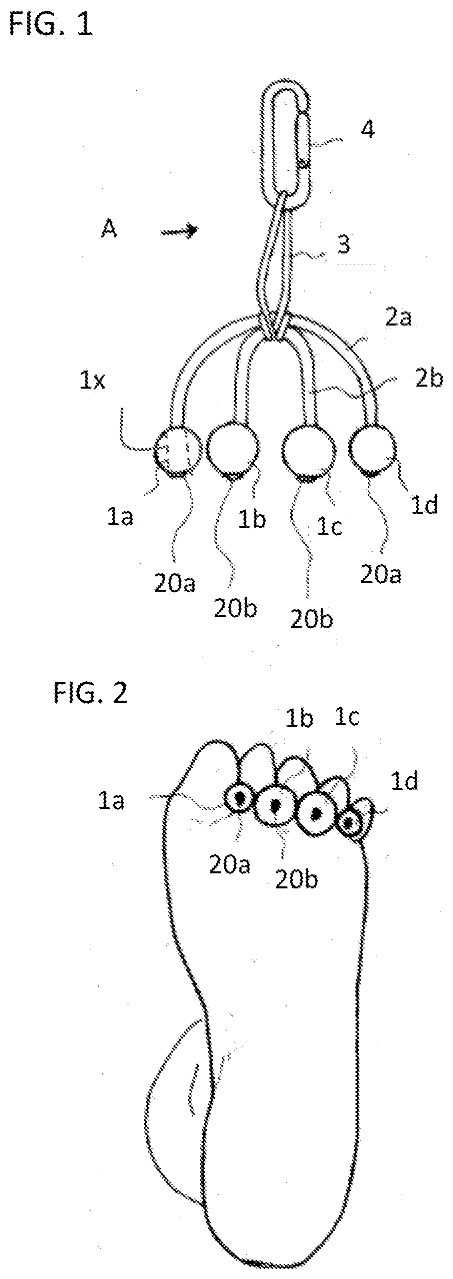
[0031]Hereinafter, the exercise equipment of the present invention is explained with references to the examples. FIG. 1 is an exercise equipment A according to a first example of the present invention. The exercise equipment A has two non-stretchable strings 2a, 2b, each having a predetermined length. To both ends of each of the two strings, four spheres 1a, 1b, 1c and 1d are attached as pressing members in a loosely fitted state. To an intermediate portion of the two strings 2a, 2b, one end of a non-stretchable connecting member 3 having a predetermined length is attached. The other end of the non-stretchable connecting member 3 is provided with a carabiner as a fixing member 4 in order to fix the exercise equipment A to an attached body such as an exercise tool body.

[0032]In this example, the strings 2a and 2b are held between all five fingers of a hand or foot of the user such that the spheres are positioned on the side of the palm or the sole. Four wooden spheres 1a, 1b, 1c, and...


PUM


Abstract

The present invention discloses an exercise equipment that enables a movement of the wrist and ankle while using portions between fingers of the hands and or foot, or using a pinching force of the adjacent fingers. The exercise equipment includes: a first string member 2a made of a first non-stretchable string, the first string member having a first length; a first pressing member 1a made of a hard material attached to one end of the first string member; a second pressing member 1d made of the hard material attached to the other end of the first string member; a connecting member 3 of being non-stretchable having a second length, the connecting member has a first end and a second end, the first end connected to an intermediate portion of the first string 2a; and a fixing member 4 provided at the other end of the connecting member 3.

Description

TECHNICAL FIELD[0001]The present invention relates to an exercise equipment that enables a movement of the wrist and ankle while using portions between fingers of the hands and or foot, or using a pinching force of the adjacent fingers. This exercise equipment enables, for example, a fluid movement of the hip joint and a rowing movement of the scapula. With this exercise equipment, for example, whole body exercise can be carried out even in a lying posture so that the spine is not tense.BACKGROUND OF THE INVENTION[0002]As shown in FIG. 7, there is a conventional Pilates type exercise tool for enabling a whole body exercise. This tool can enable an exercise even in a lying position to imitate an indoor exercise of moving the hip joint by riding a bicycle, or a rowing exercise when pulling a rope. This can restore the limb movement, the hip fluidity, the spine movement, the scapula fluidity, and the neck movement. This exercise equipment has become available to people because it allow...

Claims


Application Information

Patent Timeline
Patent Type & Authority Applications(United States)
IPC IPC(8): A63B21/00
CPCA63B21/4039A63B21/151A63B21/4035A63B21/4034
Inventor OZEKI, TAKASHI
Owner OZEKI TAKASHI
Why Eureka
Try Eureka