Braking/driving force control apparatus for a vehicle

Active Publication Date: 2021-09-16
TOYOTA JIDOSHA KK
View PDF0 Cites 0 Cited by
  • Summary
  • Abstract
  • Description
  • Claims
  • Application Information

AI Technical Summary

Benefits of technology

[0042]Therefore, as the pedal device in which the third link is the connecting link, the ratio of the pivot angle of the second link to the pivot angle of the first link can be maximized when the pivot angle of the first link is the refe

Problems solved by technology

Therefore, not only the change amount of the acceleration/deceleration of the vehicle cannot be changed with respect to the change amount of the pedal stroke, but it becomes difficu

Method used


Image

  • Braking/driving force control apparatus for a vehicle
  • Braking/driving force control apparatus for a vehicle
  • Braking/driving force control apparatus for a vehicle

Examples


Example

First Embodiment

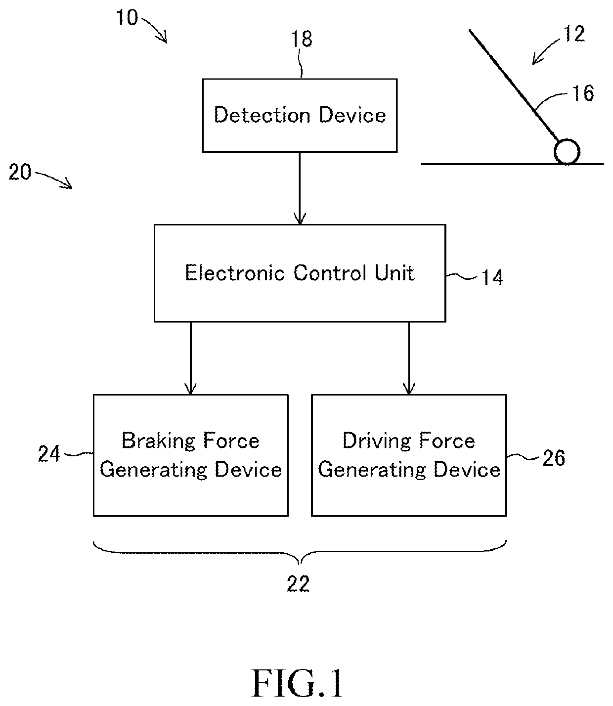
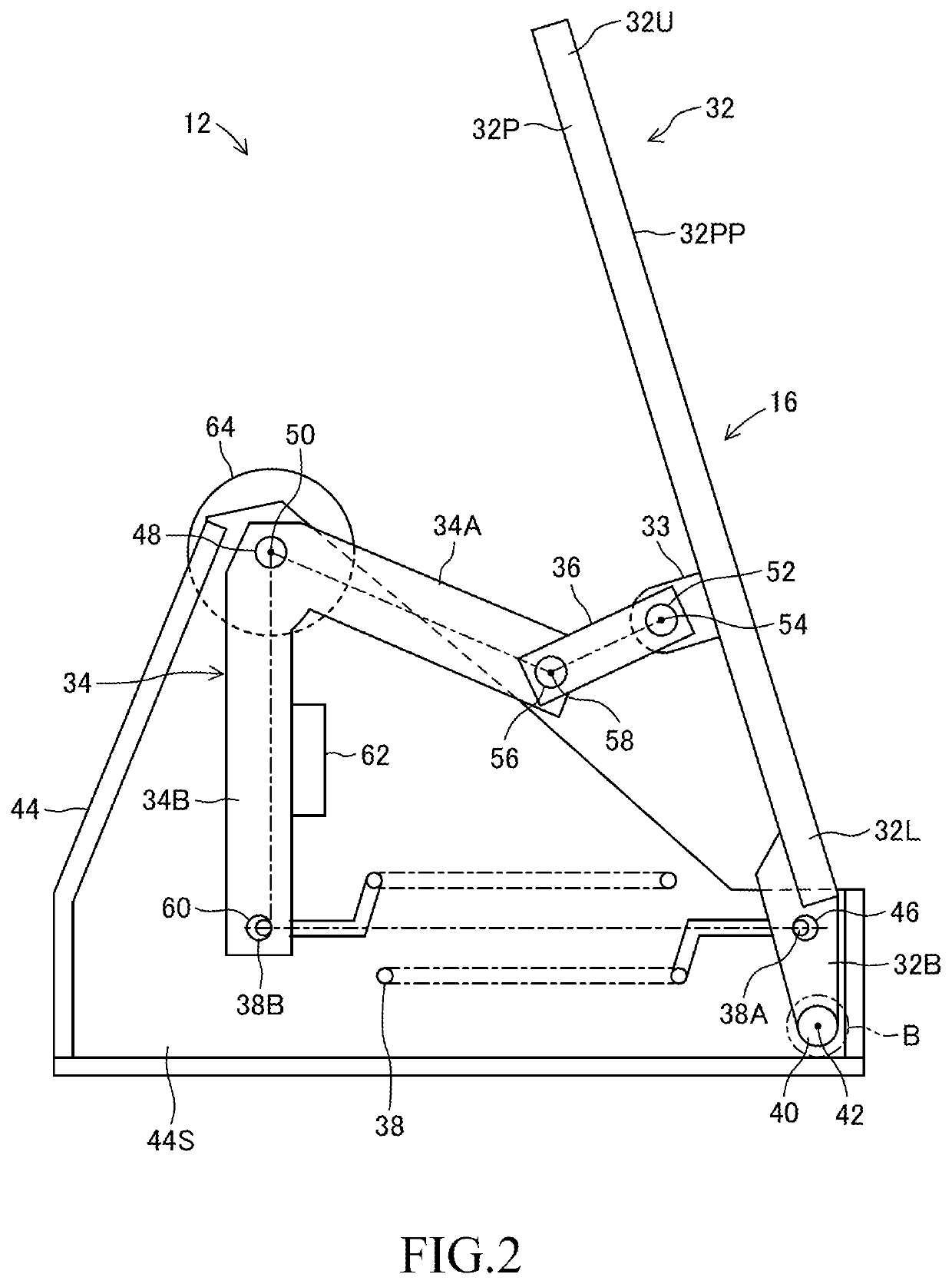
[0054]The braking / driving force control apparatus 10 for a vehicle according to the first embodiment includes a pedal device 12 and an electronic control unit 14, and the electronic control unit is hereinafter abbreviated as an ECU. The pedal device 12 includes an input member 16 that is depressed by a driver not shown in the drawing, and a detection device 18 which is configured to detect an amount of depression applied to the input member. The detailed structure of the pedal device 12 will be described later with reference to FIG. 2. The ECU 14 is configured to calculate a target braking / driving force Fbdt of a vehicle 20 based on the depression amount detected by the detection device 18, and control a braking / driving force generating device 22 so that a braking / driving force Fbd of the vehicle becomes the target braking / driving force Fbdt.

[0055]The braking / driving force generating device 22 includes a braking force generating device 24 and a driving force generati...

Example

Second Embodiment

[0088]FIG. 4 is a side view showing a pedal device in a second embodiment of the vehicle braking / driving force control device according to the present disclosure. In FIG. 4, the same members as those shown in FIG. 2 are designated by the same reference numerals as those shown in FIG. 2.

[0089]In the second embodiment, the first link 32 is configured similarly to the first link 32 in the first embodiment, but the third link 36 which is the connecting link in the first embodiment is not provided. A roller contact member 72 having a roller contact surface 72S is fixed to the lower surface 32PR on the side opposite to the pedaling surface 32PP.

[0090]A roller support shaft 74 is integrally provided at the tip of the first arm portion 34A of the second link 34, and an axis 76 (a fifth axis) of the roller support shaft extends parallel to the second axis 50. The roller support shaft 74 supports a roller 78 rotatably about the fifth axis 76, and a surface of the roller 78 ex...


PUM


Abstract

A pedal device includes a first link, a second link, and a return spring that biases the first link toward a standard position at which a pivot angle of the first link is zero. A ratio of a pivot angle of the second link to the pivot angle of the first link is maximum when the pivot angle of the first link is a reference angle. A target acceleration/deceleration of a vehicle is calculated so that in the range in which the pivot angle of the first link is smaller than the reference angle, a target deceleration of the vehicle increases as the pivot angle of the first link is smaller, and in the range in which the pivot angle of the first link is larger than the reference angle, a target acceleration of the vehicle increases as the pivot angle of the first link increases.

Description

CROSS-REFERENCE TO RELATED APPLICATION[0001]This application claims priority to Japanese Patent Application No. JP2020-040908 filed on Mar. 10, 2020, the content of which is hereby incorporated by reference in its entirety into this application.BACKGROUND1. Technical Field[0002]The present disclosure relates to a braking / driving force control apparatus for a vehicle such as an automobile.2. Description of the Related Art[0003]In vehicles such as automobiles, there is known a so-called one-pedal type pedal device that is operated by a driver to control a braking force and a driving force of the vehicle. In a braking / driving force control apparatus for a vehicle including a one-pedal type pedal device, a control unit calculates a target acceleration / deceleration of the vehicle according to an amount of depression of the pedal device, and controls a braking / driving force generating device so that acceleration / deceleration of the vehicle becomes the target acceleration / deceleration.[000...

Claims


Application Information

Patent Timeline
IPC IPC(8): B60W30/18B60T7/04B60K26/02B60W10/04B60W10/18
CPCB60W30/18181B60T7/042B60K26/02B60W10/04B60W2540/12B60W2710/00B60W2710/18B60W2540/10B60W10/18B60T7/06G05G1/44G05G1/38G05G5/03
Inventor ISONO, HIROSHI
Owner TOYOTA JIDOSHA KK
Why Eureka
Try Eureka