Automobile hub machining positioning system and intelligent cleaning and precision machining production line

A technology for automobile hubs and positioning systems, which is applied in the direction of wheels, metal processing, and positioning devices, which can solve the problems of positioning accuracy errors, high processing costs, and unreliability, and achieve improved processing accuracy, good self-locking performance, and reliable clamping Effect

Active Publication Date: 2022-01-21
QINGDAO TECHNOLOGICAL UNIVERSITY +1
View PDF11 Cites 0 Cited by
  • Summary
  • Abstract
  • Description
  • Claims
  • Application Information

AI Technical Summary

Problems solved by technology

[0002] At present, the hub positioning error in the field of automobile hub machining is relatively large, which seriously affects the machining accuracy of the hub, and cannot adapt to the clamping of various hub sizes, resulting in extremely low flexibility of the hub machining unit; for example: in the invention CN201711405456.6 Disclosed is an automobile hub clamp, which drives the clamping parts to clamp the hub rim through a horizontal telescopic rod, and adapts to different hub sizes by controlling the rotation and elevation of the hub platform. However, controlling the rotation and elevation of the hub platform adapts to different sizes The size of the wheel hub is easy to cause a large positioning accuracy error, the clamping groove on the clamping piece is not adaptable, the thickness of the rim of the wheel hub is small, and the clamping force generated by the clamping piece on the hub is too concentrated, which is easy to deform the wheel hub or unreliable clamping
Another example: a hub fixture is disclosed in the utility model CN201720017875.1. This fixture needs to manually

Method used


Image

  • Automobile hub machining positioning system and intelligent cleaning and precision machining production line
  • Automobile hub machining positioning system and intelligent cleaning and precision machining production line
  • Automobile hub machining positioning system and intelligent cleaning and precision machining production line

Examples


Example Embodiment

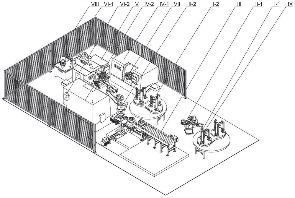
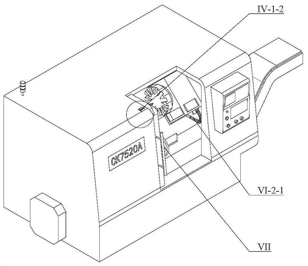
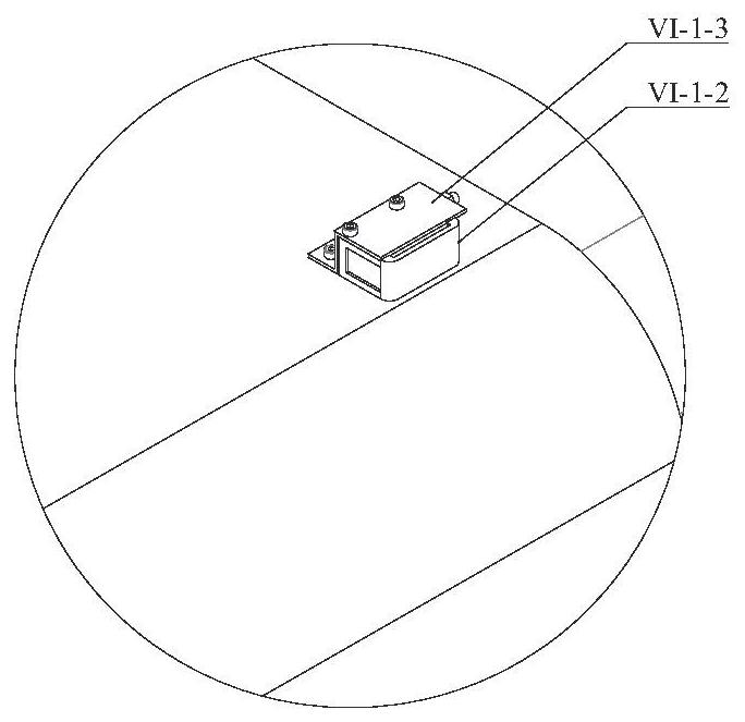
[0053] like figure 1 As shown, the car hub intelligent clean precision processing line proposed by the present embodiment is from the first shelf I-1, the second bracket I-2, the first robot II-1, the second robot II-2, the automatic hub three-dimensional Scanning device III, first horizontal lathe IV-1, second horizontal lathe IV-2, machining center V, trace lubricating fuel tank VI-1, trace lubricating apparatus VI-2, positioning system VII, protective fence VIII composition.

[0054] Among them, the protective fence VIII is disposed outside the first horizontal lathe IV-1, the second horizontal lathe IV-2, the outer side of the trace lubricating oil supply box Vi-1, and arranges the lower material frame along the second robot II-2. II-2, first horizontal lathe IV-1, second horizontal lathe IV-2, machining center V, automatic hub three-dimensional scanning device III, second robot II-2 and first horizontal lathe IV-1, The line IV-2 and the linear distance between the machining c...


PUM


Abstract

The invention discloses an automobile hub machining positioning system and an intelligent cleaning and precision machining production line. The automobile hub machining positioning system comprises an upper-layer mounting plate and a lower-layer mounting plate which are vertically connected together and spaced by a set distance. At least three U-shaped blocks are fixed on the top surface of the upper-layer mounting plate in the circumferential direction of the upper-layer mounting plate, an L-shaped bracket is mounted between every two adjacent U-shaped blocks, a ball head with a screw rod is mounted on each L-shaped bracket, and the L-shaped brackets are driven by a first driving device to move in the radial direction of the upper-layer mounting plate; and a slidable chuck is installed in each U-shaped block, the bottom of each chuck is connected with an ejector rod assembly, and the ejector rod assemblies are driven by a second driving device to drive the chucks to move in the radial direction of the upper-layer mounting plate. Three wedge blocks are fixed on the top surface of the lower-layer mounting plate in the circumferential direction of the lower-layer mounting plate, and the three wedge blocks are driven by a third driving device to move in the radial direction of the lower-layer mounting plate; and the inclined faces of the wedge blocks are matched with the bottoms of the ejector rod assemblies.

Description

Technical field [0001] The present invention relates to the technical field of machining equipment, and a vehicle hub positioning system and a car hub intelligent clean and precision processing line including the positioning system are designed. Background technique [0002] At present, the wheel positioning error in the field of automotive hub machine is large, which seriously affects the machining accuracy of the hub, and cannot accommodate the clamping of a variety of hub size, resulting in extremely low degree of flexibility in the hub machining unit; for example: inventive CN201711405456.6 An automotive hub clamp is disclosed, and the hub rod is clamped by a horizontal stretch lever, and the hub rib is clamped, and the rotation elevation of the hub platform is adapted to different hub size, however, the rotational lift of the control hub platform adapts to different sizes. The hub size is likely to cause a larger positioning accuracy error, and the clamping groove on the cla...

Claims


Application Information

Patent Timeline
IPC IPC(8): B23B5/00B23B25/06B23B15/00B23Q11/10
CPCB23B5/00B23B25/06B23Q7/00B23Q11/10B23B5/02B23B2250/12B23B2260/128B23B31/1261B23B2260/146B23B2260/096B23B31/16195B23B31/16216B23Q3/082B23B2215/08B23P15/00B23Q3/062B23Q7/05B23Q7/1426B23B31/18
Inventor 李长河刘德伟周宗明吴启东卢秉恒刘波陈云曹华军毛聪
Owner QINGDAO TECHNOLOGICAL UNIVERSITY
Why Eureka
Try Eureka