Control device and control method for induction motor

a control device and induction motor technology, applied in the direction of dynamo-electric converter control, dynamo-electric gear control, dynamo-electric brake control, etc., can solve the problem that the actual rsub>r /sub>compared to a nominal value may even increase to more than 20%, and the control system loses control. the effect of improving the stability of control

Active Publication Date: 2021-09-23
ORMON CORP
View PDF0 Cites 2 Cited by
  • Summary
  • Abstract
  • Description
  • Claims
  • Application Information

AI Technical Summary

Benefits of technology

[0028]The effect of the present application is: capable of avoiding the use of the slip frequency ωs, which generates an error when being subjected to a resistance change, for calculation, and accordingly, a control system can run outside an unstable area, and stability of control by the control device is improved.

Problems solved by technology

When vector control is performed on a motor, it is sometimes difficult to install a sensor for detecting the rotor speed in the motor, or a sensor is not installed to reduce costs, and vector control is performed on the motor without a speed sensor.
When the speed estimation value ω1 is located in the unstable area, it may cause the control system to lose control.
When the motor runs and generates heat, an error of the actual Rr compared to a nominal value may even increase to more than 20%.
Therefore, the control system may still run in the unstable area, so as to cause the control system to lose control.

Method used


Image

  • Control device and control method for induction motor
  • Control device and control method for induction motor
  • Control device and control method for induction motor

Examples


embodiment 1

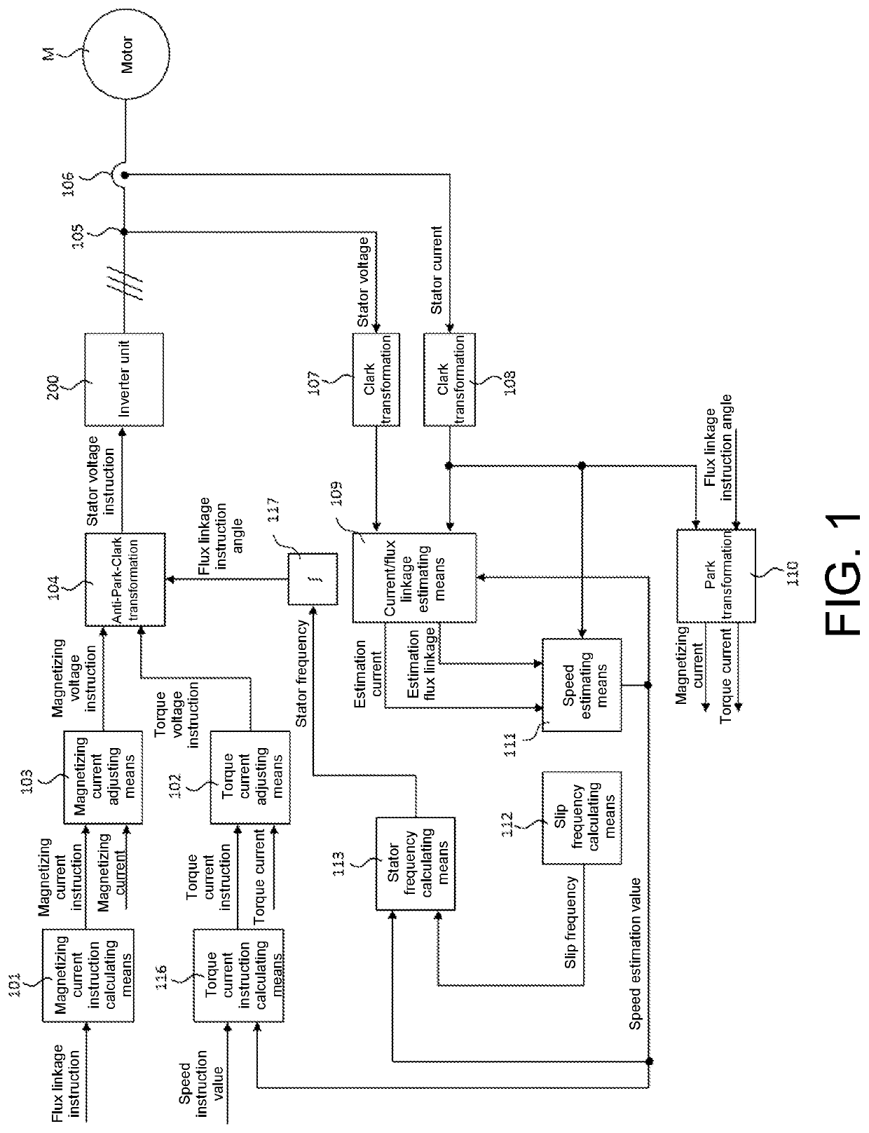
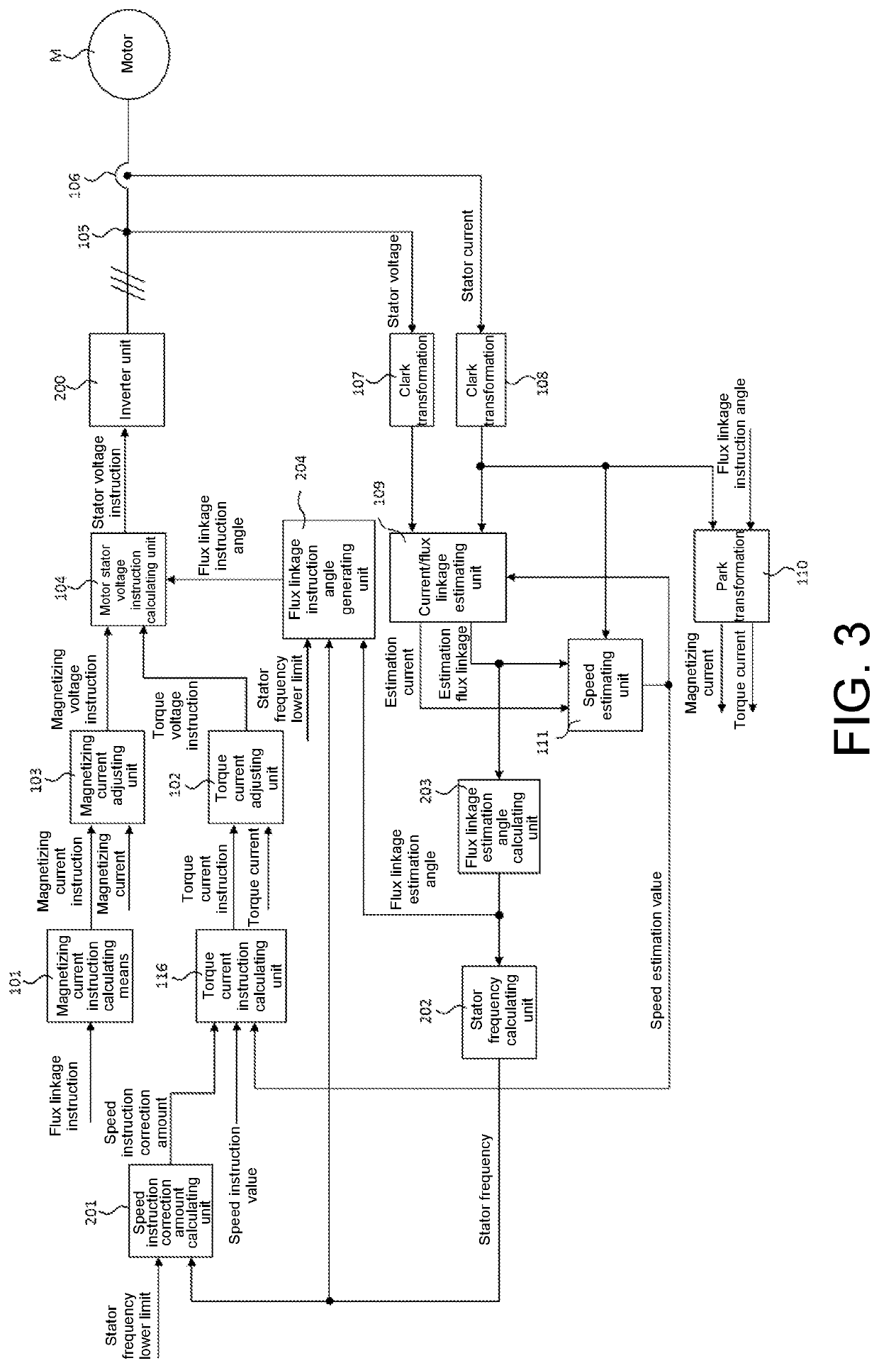
[0041]An embodiment of the present application provides a control device for an induction motor. FIG. 3 is a schematic diagram of a control device of the present embodiment.

[0042]As shown in FIG. 3, a control device 30 for an induction motor controls a stator voltage inputted to a motor M according to a flux linkage instruction, a speed instruction value, and a stator frequency lower limit inputted to the control device 30, so as to perform vector control on the motor M.

[0043]As shown in FIG. 3, the control device 30 for the induction motor includes: a magnetizing current adjusting unit 103, a torque current adjusting unit 102, a flux linkage instruction angle generating unit 204, and a motor stator voltage instruction calculating unit 104.

[0044]As shown in FIG. 3, the magnetizing current adjusting unit 103 may calculate a magnetizing voltage instruction according to a magnetizing current instruction and a magnetizing current.

[0045]The torque current adjusting unit 102 may calculate...

embodiment 2

[0087]Embodiment 2 of the present application provides a control method for an induction motor, and such control method corresponds to the control device 30 of Embodiment 1.

[0088]FIG. 9 is a schematic chart of a control method for an induction motor of this embodiment, and as shown in FIG. 9, the method includes:

step 901: calculating a magnetizing voltage instruction;

step 902: calculating a torque voltage instruction;

step 903: calculating a flux linkage instruction angle according to a lower limit of a preset stator frequency, a stator frequency, and a flux linkage estimation angle; and

step 904: calculating, according to the magnetizing voltage instruction, the torque voltage instruction, and the flux linkage instruction angle, a stator voltage instruction for controlling stator operation of the motor.

[0089]Description related to each step of the control method may be found with reference to the description of corresponding units of Embodiment 1. Besides, the control method may furt...


PUM


Abstract

A control device and a control method for an induction motor. The control device comprises: a magnetizing current adjusting unit used for calculating a magnetizing voltage instruction; a torque current adjusting unit used for calculating a torque voltage instruction; a flux linkage instruction angle generating unit calculating a flux linkage instruction angle according to a lower limit ω1th of a preset stator frequency, a stator frequency ω1, and a flux linkage estimation angle; and a motor stator voltage instruction calculating unit calculating, according to the magnetizing voltage instruction, the torque voltage instruction, and the flux linkage instruction angle, a stator voltage instruction for controlling a stator of the motor. The control system can be run outside an unstable area, and the stability of control by the control device is improved.

Description

BACKGROUNDTechnical Field[0001]The present application relates to a field of motor technology, and in particular, to a control device and a control method for an induction motor.Description of Related Art[0002]When vector control is performed on a motor, it is sometimes difficult to install a sensor for detecting the rotor speed in the motor, or a sensor is not installed to reduce costs, and vector control is performed on the motor without a speed sensor.[0003]FIG. 1 is a system block diagram of vector control performed on a motor without a speed sensor in the related art. As shown in FIG. 1,a magnetizing current instruction calculating means 101 generates a magnetizing current instruction according to an inputted flux linkage instruction;a magnetizing current adjusting means 103 obtains a magnetizing voltage instruction according to the magnetizing current instruction and a magnetizing current fed back by a park transformation means 110;a torque current instruction calculating mean...

Claims


Application Information

Patent Timeline
Patent Type & Authority Applications(United States)
IPC IPC(8): H02P21/30H02P21/18H02P21/14H02P21/22
CPCH02P21/30H02P21/18H02P2207/01H02P21/22H02P21/141H02P21/28
Inventor WANG, YUTAOLIU, SHAOFENG
Owner ORMON CORP
Why Eureka
Try Eureka