Control device of power transmission device

a technology of power transmission device and control device, which is applied in the direction of safety/regulatory device, servomotor components, gearing, etc., can solve the problems of difficult to appropriately move the secondary element, difficult to specify or predict, and lack of flexibility, so as to improve the robustness of the control of the secondary power, the stability of the sequential determination of the control input determining unit, and the effect of improving the stability of the control inpu

Active Publication Date: 2014-03-13
HONDA MOTOR CO LTD
View PDF1 Cites 4 Cited by
  • Summary
  • Abstract
  • Description
  • Claims
  • Application Information

AI Technical Summary

Benefits of technology

[0039]Therefore, the stability of the control input sequentially determined by the control input determining unit is improved. Consequently, it becomes possible to further improve the robustness of the control of the secondary power.

Problems solved by technology

However it lacks flexibility under various external environments in which a position or a shape of an external object contacting the secondary element, or a disturbance and the like, is difficult to specify or predict beforehand.
For example, in a case where the secondary element contacts an unpredicted external object and the like, situations where it becomes difficult to appropriately move the secondary element, or situations where an excessive external force acts on the secondary element, tends to occur.
Consequently, the gradient of the switching hyperplane set in advance by the above mentioned methods may become inappropriate in some operational situation of the power transmission device, and there is a possibility of losing robustness of the control in such operational situation of the power transmission device.

Method used


Image

  • Control device of power transmission device
  • Control device of power transmission device
  • Control device of power transmission device

Examples


first embodiment

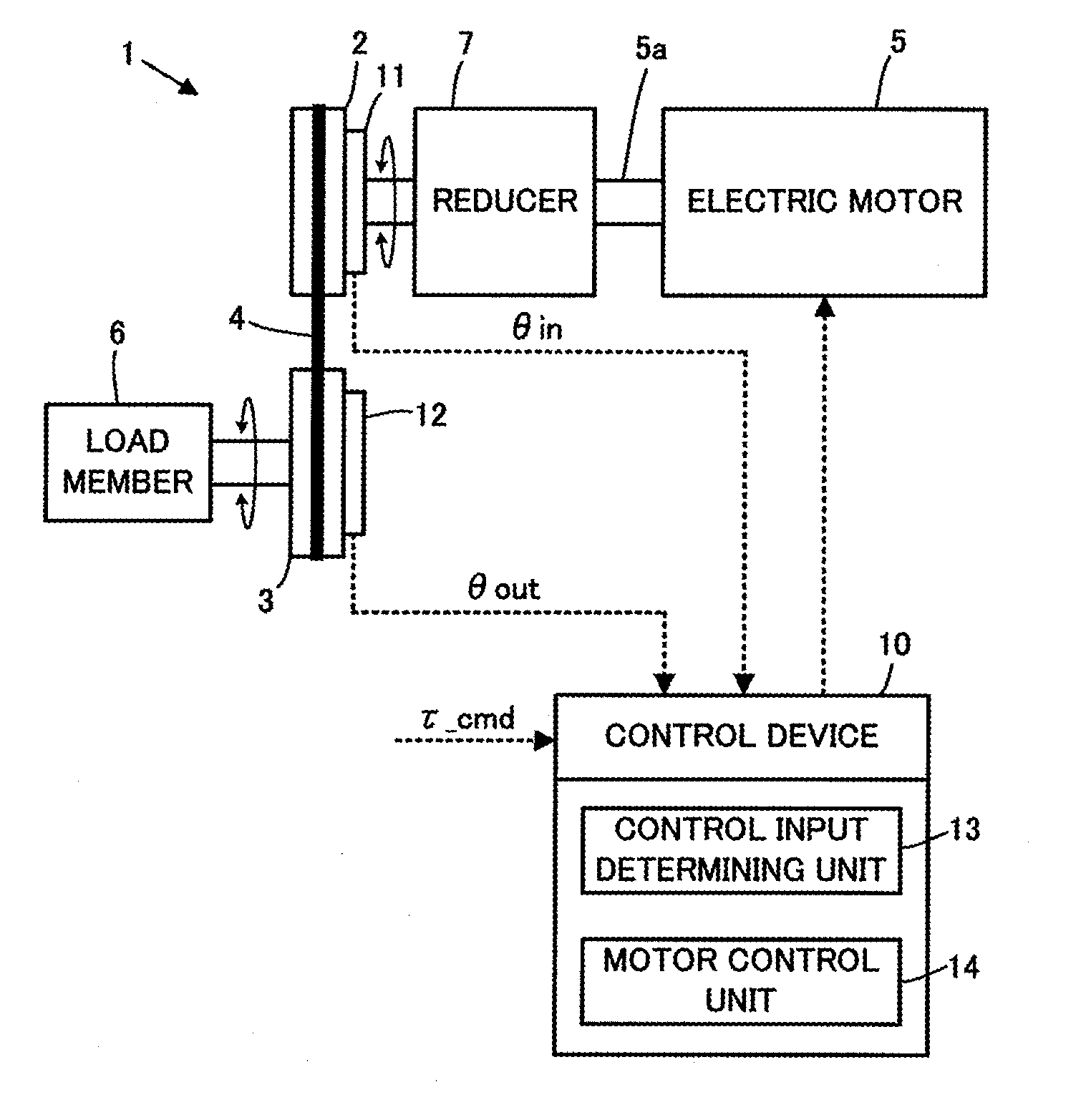
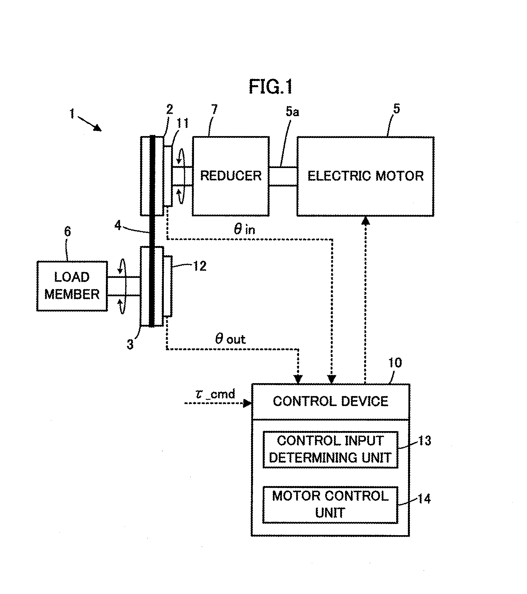
[0053]A first embodiment of the present invention will be explained below with reference to FIG. 1 through FIG. 6.

[0054]As is shown in FIG. 1, a power transmission device 1 of the present embodiment is equipped with a drive pulley 2 as a primary element, a driven pulley 3 as a secondary element, a wire 4 which performs rotational transmission between the pulleys 2, 3, an electric motor 5 as an actuator for imparting a rotational driving force to the drive pulley 2, and a load member 6 fixed to the driven pulley 3 so as to rotate integrally with the driven pulley 3.

[0055]In FIG. 1, the load member 6 is described as an integrated structure. However, it is not limited to an integrated structure. For example, the load member 6 may be the one in which a plurality of members are coupled by joints and the like (for example, a link mechanism having a plurality of joints, and the like).

[0056]The drive pulley 2 is connected to an output shaft 5a of the motor 5 via a reducer 7. Further, the dr...

second embodiment

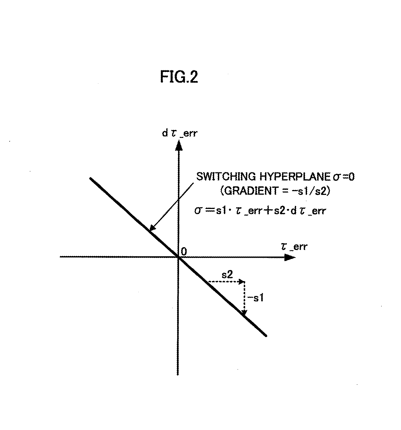
[0208]Next, a second embodiment of the present invention will be explained with reference to FIG. 7. In the present embodiment, a part of the processing of the control input determining unit 13 of the control device 10 differs from the first embodiment. Therefore, explanation of the present embodiment will be made mainly for matters differing from the first embodiment, and explanation of matters identical with the first embodiment will be omitted.

[0209]In the present embodiment, in order to reduce the influence of disturbance in the processing of the control input determining unit 13, the values of the secondary torque deviation τ_err and the secondary torque deviation velocity dτ_err are sequentially estimated using an observer. Thereafter, in place of the actual secondary torque deviation τ_err_act calculated using the actual secondary torque τ_act (the estimated value by the secondary torque detecting unit 13f) as it is, and the actual secondary torque deviation velocity dτ_err_a...

third embodiment

[0223]Subsequently, a third embodiment of the present invention will be explained with reference to FIG. 8 through FIG. 11. The present embodiment differs from the first embodiment in the configuration of a part of the power transmission device, and a part of the control processing. Therefore, explanation of the present embodiment will be mainly on the matters differing from the first embodiment, and the matters identical with the first embodiment will be omitted.

[0224]With reference to FIG. 8, a power transmission device 21 of the present embodiment is equipped with, similarly to the power transmission device 1 of the first embodiment, the drive pulley 2, the driven pulley 3, the wire 4, the electric motor 5, and the load member 6. Further, the power transmission device 21 is configured to rotate and drive the driven pulley 3 together with the load member 6, by transmitting the rotational driving force (torque) imparted to the drive pulley 2 from the output shaft 5a of the electric...


PUM


Abstract

By a control processing of the sliding-mode control using a switching function configured from a first variable component, which is a deviation between an observed value and a desired value of a secondary power imparted to a secondary element (3) from a primary element (2) via an elastic deformation member (4), and a second variable component which is a temporal change rate of the deviation, so as to sequentially determine a control input to control an actuator (5) to converge the first variable component to zero on a switching hyperplane. A gradient of the switching hyperplane is set such that a time constant corresponding to the gradient of the switching hyperplane is equal to or larger than a given specific time constant.

Description

BACKGROUND OF THE INVENTION[0001]1. Field of the Invention[0002]The present invention relates to a control device of a power transmission device which drives a joint and the like of a robot.[0003]2. Description of the Related Art[0004]Conventionally, in an industrial robot and the like, a position control (a servo control) is generally performed, in order to drive a joint as a power transmission device between a primary element (a driving element) and a secondary element (a driven element). Further, as a control method for the position control, a technique which adopts a sliding-mode control, for example, in Japanese Patent Application Laid-Open No. H5-134758 (hereinafter referred to as Patent Document 1) is proposed. In this technique, a switching function used for the sliding-mode control is determined by a format of proportional integral control.[0005]In the position control of the power transmission device such as the joint, the position of the secondary element (the driven elem...

Claims


Application Information

Patent Timeline
Patent Type & Authority Applications(United States)
IPC IPC(8): F15B13/02
CPCF15B13/02F16H9/04
Inventor ORITA, ATSUO
Owner HONDA MOTOR CO LTD
Why Eureka
Try Eureka