Ultrasound system and method of controlling ultrasound system
- Summary
- Abstract
- Description
- Claims
- Application Information
AI Technical Summary
Benefits of technology
Problems solved by technology
Method used
Image

Examples
embodiment 1
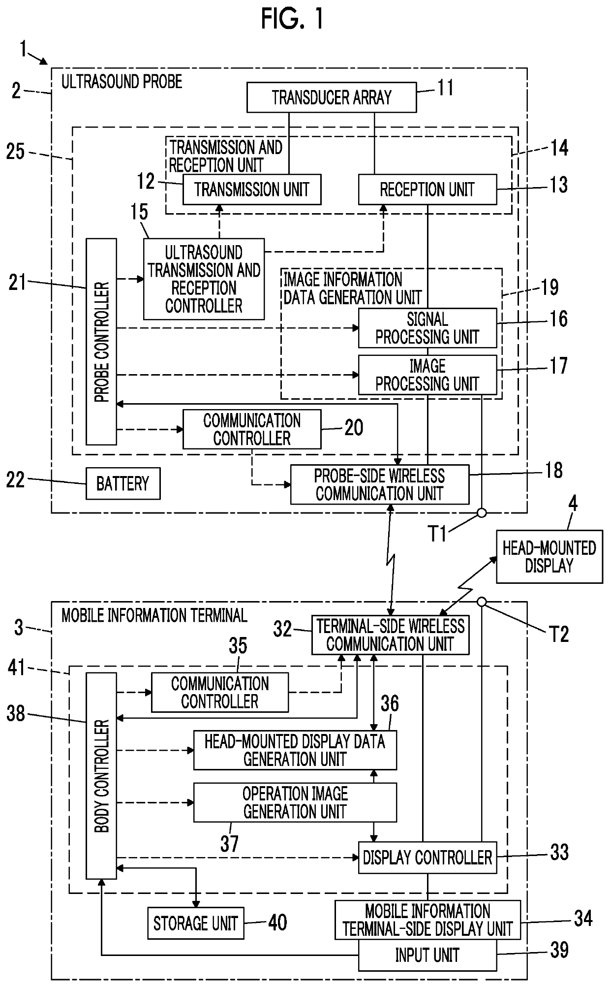
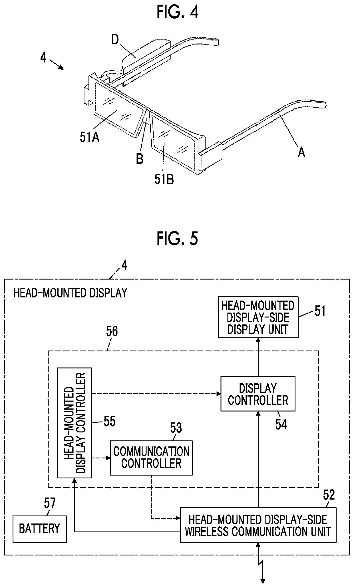
[0052]FIG. 1 shows the configuration of an ultrasound system 1 according to Embodiment 1 of the invention. The ultrasound system 1 comprises an ultrasound probe 2, a mobile information terminal 3, and a head-mounted display 4. The ultrasound probe 2 and the head-mounted display 4 are connected to the mobile information terminal 3 by wireless communication. The head-mounted display 4 is a display device that is mounted on a head of a user and is viewed by the user who mounts the head-mounted display 4, an ultrasound image and the like are transmitted from the mobile information terminal 3 to the head-mounted display 4 in a wireless manner, and the transmitted ultrasound image and the like are displayed on the head-mounted display 4.
[0053]As shown in FIG. 1, the ultrasound probe 2 comprises a transducer array 11, and a transmission unit 12 and a reception unit 13 are connected to the transducer array 11. The transmission unit 12 and the reception unit 13 form a transmission and recept...
embodiment 2
[0143]In Embodiment 1, although the user performs the input operation through the input unit 39 of the mobile information terminal 3, the input operation can be performed based on voice of the user.
[0144]As shown in FIG. 9, a head-mounted display 4A of Embodiment 2 is additionally provided with a microphone M and comprises a head-mounted display controller 55A instead of the head-mounted display controller 55 compared to the head-mounted display 4 of Embodiment 1 shown in FIG. 5. In the head-mounted display 4A, the head-mounted display-side wireless communication unit 52 and the head-mounted display controller 55A are connected to the microphone M. The communication controller 53, the display controller 54, and the head-mounted display controller 55A constitute a head-mounted display processor 56A.
[0145]The microphone M of the head-mounted display 4A acquires the voice of the user. The microphone M acquires the voice of the user as an analog signal and converts the acquired voice in...
embodiment 3
[0151]In Embodiment 2, although the input operation is performed based on the voice of the user, for example, the input operation can be performed based on movement of the eyes of the user, such as a wink or movement of a line of sight of the user.
[0152]As shown in FIG. 11, a head-mounted display 4B of Embodiment 3 comprises an eye camera unit C1 instead of the microphone M and comprises a head-mounted display controller 55B instead of the head-mounted display controller 55A compared to the head-mounted display 4A of Embodiment 2 shown in FIG. 11.
[0153]In the head-mounted display 4B, the head-mounted display-side wireless communication unit 52 and the head-mounted display controller 55B are connected to the eye camera unit C1. The communication controller 53, the display controller 54, and the head-mounted display controller 55B constitute a head-mounted display processor 56B.
[0154]The eye camera unit C1 of the head-mounted display 4B continuously generates an eye image obtained by ...
PUM
 Abstract
Description
Claims
Application Information
 - Generate Ideas
- Intellectual Property
- Life Sciences
- Materials
- Tech Scout
- Unparalleled Data Quality
- Higher Quality Content
- 60% Fewer Hallucinations
Browse by: Latest US Patents, China's latest patents, Technical Efficacy Thesaurus, Application Domain, Technology Topic, Popular Technical Reports.
© 2025 PatSnap. All rights reserved.Legal|Privacy policy|Modern Slavery Act Transparency Statement|Sitemap|About US| Contact US: help@patsnap.com