
Image forming apparatus

Active Publication Date: 2021-09-30
CANON KK
View PDF0 Cites 0 Cited by
  • Summary
  • Abstract
  • Description
  • Claims
  • Application Information

AI Technical Summary

Benefits of technology

The patent text describes a technique that can minimize density unevenness with very precise results. This means that the technique can control the thickness of materials in a way that ensures everything is even and aligned properly.

Problems solved by technology

In an electrophotographic image forming apparatus, there may occur variation in tint of an output image due to, for example, variation in use environment such as temperature and humidity, performance degradation caused by aging or reduced durability of members.
In addition, sensitivity unevenness on a photosensitive drum, edge drop of an amount of laser light emitted onto the photosensitive drum, lens aberration of an optical system being used, uneven transfer during a transfer process, or the like, may cause density unevenness or color unevenness in an output image.
However, density unevenness cannot be suppressed with a high accuracy unless the correction value is an appropriate value.

Method used


Image

  • Image forming apparatus
  • Image forming apparatus
  • Image forming apparatus

Examples


first embodiment

[0019]

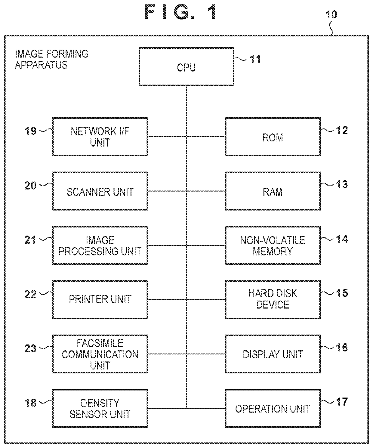
[0020]FIG. 1 is a block diagram illustrating a general hardware configuration example of an image forming apparatus 10 according to a first embodiment. The image forming apparatus 10, including an image forming function (print function) of performing image formation on a printing material such as a printing sheet, is configured as a multi-function peripheral (MFP) having a function of performing various jobs such as copying, scanning, printing, or the like. A copy job is a job that optically reads an image of a document and prints a copy of the image on a printing sheet. A scan job is a job that optically reads an image of a document and stores, or transmits to an external device, the acquired image data as a file. A print job is a job that prints an image on a sheet, based on image data (print data) received from an external device such as a PC. The image forming apparatus 10 may be configured as a printing apparatus, a printer, a copying machine, or a facsimile, for example....

second embodiment

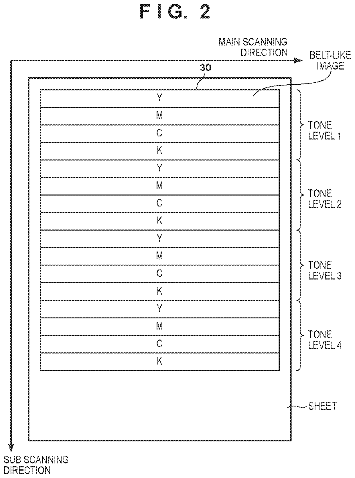
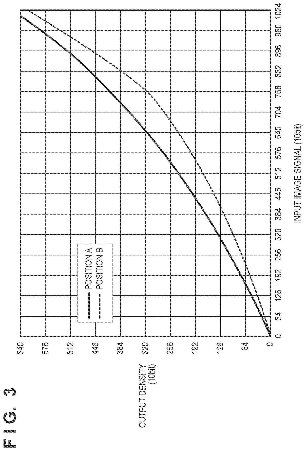
[0070]In the first embodiment, the tone characteristic indicating the relation between the input image signal and the output density is acquired based on the measurement result of the density with regard to the measurement chart 30, and the conversion coefficient N to be applied to the density difference ΔD to be corrected is determined based on the tone characteristic. As has been described above, the tone characteristic may also vary depending on the type of sheet (paper) on which the measurement chart 30 for density unevenness correction is printed. Therefore, in a second embodiment, in association with the types of sheet used for density unevenness correction, a plurality of conversion coefficient tables is preliminarily prepared, each including the conversion coefficients N corresponding to a plurality of tone levels. When performing density unevenness correction, there is used a conversion coefficient table corresponding to the type of sheet to be used. In the following, descr...


PUM


Abstract

In an image forming apparatus, an image processing unit converts image data based on a plurality of conversion conditions corresponding to a plurality of positions in a predetermined direction. A controller controls the image forming unit to form an image based on the image data converted by the image processing unit, and controls the image forming unit to form a plurality of pattern images including first, second and third pattern images. The controller controls a reading unit to read the plurality of pattern images on the sheet, generates correction conditions corresponding to the plurality of positions in the predetermined direction based on a reading result of the reading unit, and generates the plurality of conversion conditions based on the reading result and the correction conditions corresponding to the plurality of positions in the predetermined direction.

Description

BACKGROUND OF THE INVENTIONField of the Invention[0001]The present invention relates to a correction process of correcting density unevenness of an image formed by an image forming apparatus.Description of the Related Art[0002]In an electrophotographic image forming apparatus, there may occur variation in tint of an output image due to, for example, variation in use environment such as temperature and humidity, performance degradation caused by aging or reduced durability of members. In addition, sensitivity unevenness on a photosensitive drum, edge drop of an amount of laser light emitted onto the photosensitive drum, lens aberration of an optical system being used, uneven transfer during a transfer process, or the like, may cause density unevenness or color unevenness in an output image. Generally, density unevenness or color unevenness appearing in the main scanning direction may have a larger impact on the output image than that appearing in the sub scanning direction.[0003]In o...

Claims


Application Information

Patent Timeline
IPC IPC(8): G03G15/00
CPCG03G15/5062
Inventor YOKOTE, AKIHITO
Owner CANON KK
Learn More