

Alignment film transfer printing plate and manufacturing method thereof
- Summary
- Abstract
- Description
- Claims
- Application Information
AI Technical Summary
Benefits of technology
Problems solved by technology
Method used
Image

Examples
first embodiment
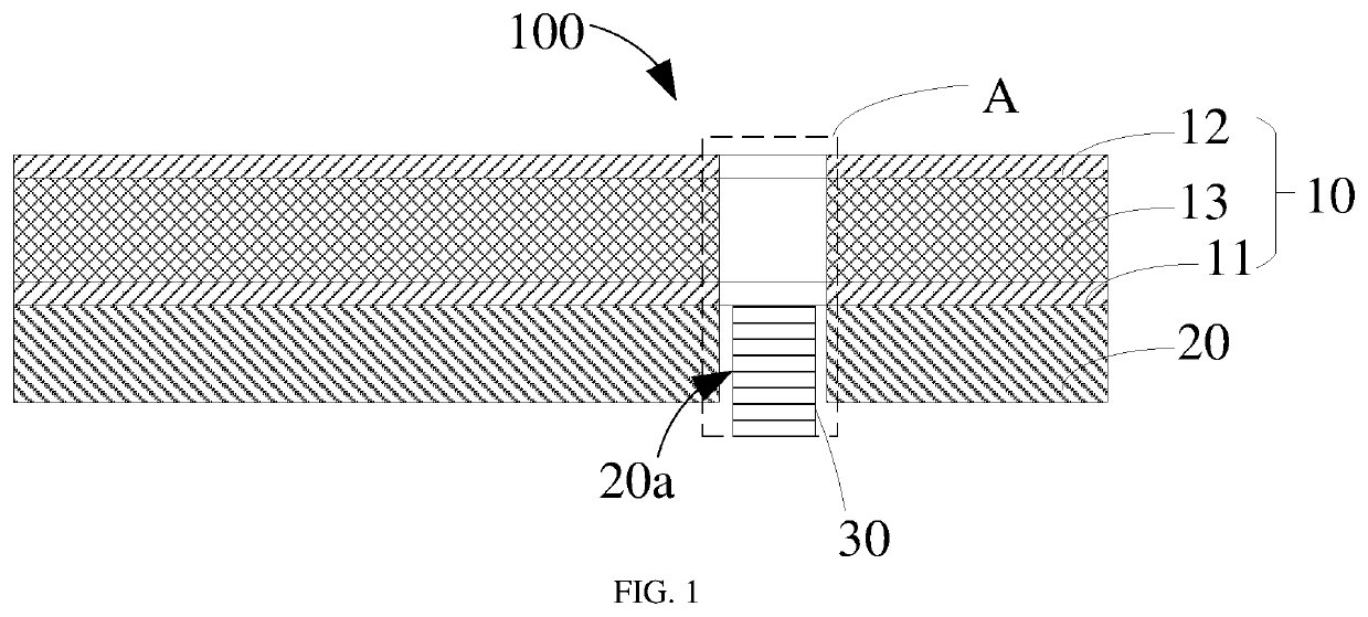
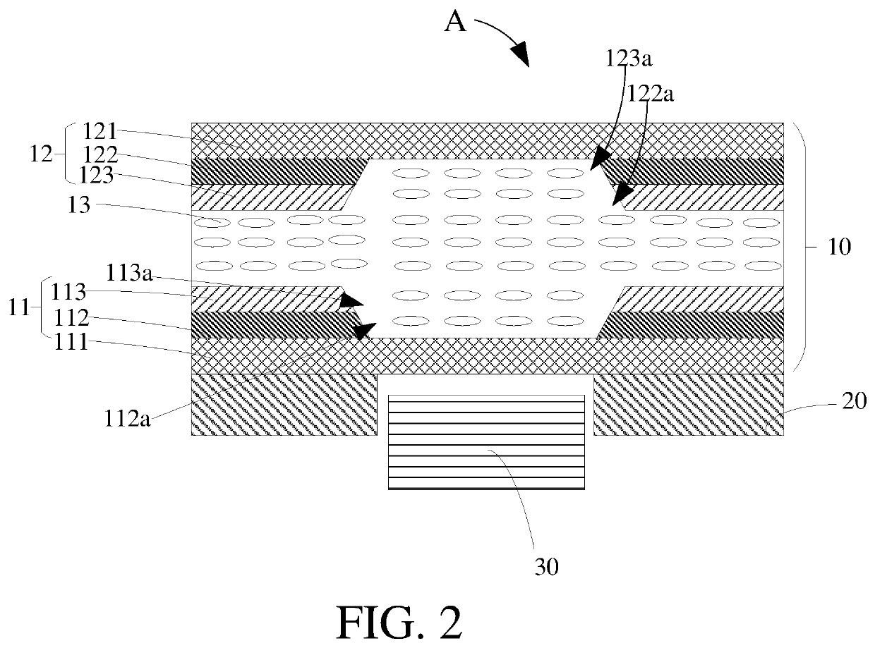
[0027]Please refer to FIG. 1 and FIG. 2, a liquid crystal display device 1 of this application includes a liquid crystal display panel 10, a backlight module 20, and a light-sensitive component 30. The backlight module 20 is disposed on a side of the liquid crystal display panel 10. A receiving portion 20a is provided in the backlight module 20. The light-sensitive component 30 is received in the receiving portion 20a. The receiving portion 20a can be a through-hole provided in the backlight module 20. The light-sensitive component 30 includes but is not limited to a front-facing camera, a face recognition light-sensitive component, and a gesture sensor, etc.
[0028]The liquid crystal display device 1 further comprises a first polarizer (not shown in the figures) disposed between the display panel 10 and the backlight module 20, and a second polarizer (not shown in the figures) disposed on the display panel 10 away from the backlight module 20. It can be understood that the liquid cry...
second embodiment
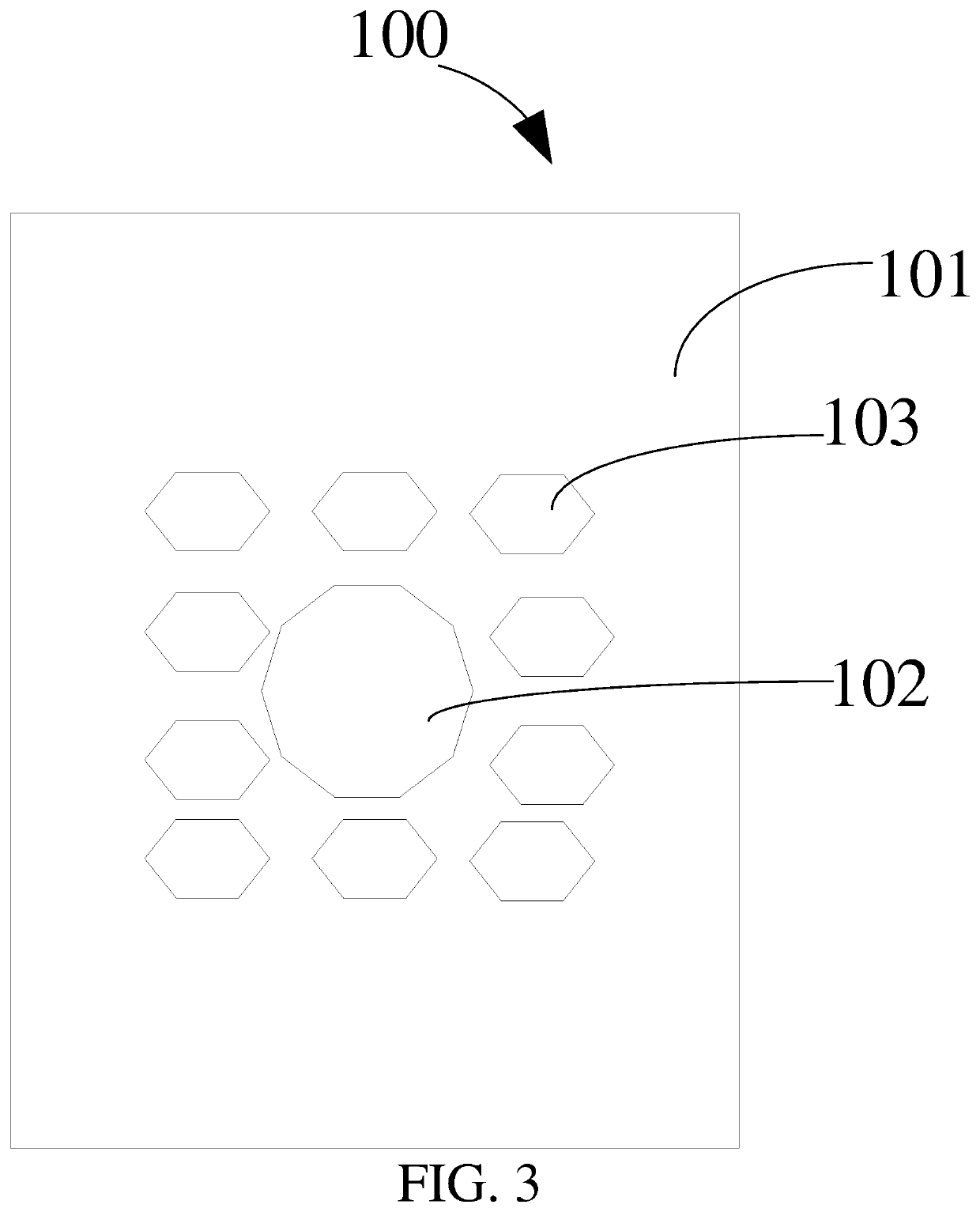
[0031]Please refer to FIG. 1 to FIG. 4 at the same time, an alignment film transfer printing plate 1 of this application can be configured to manufacture a blind-hole screen type liquid crystal display device 100 (as shown in FIG. 1 and FIG. 2). The alignment film transfer printing plate 1 is configured to prevent alignment films (such as the first alignment film 113 and the second alignment film 114) from stacking in the blind-holes (such as the first opening 112a and the third opening 122a). Hereby, the blind-holes refer to blind-holes for the liquid crystal display device 100.
[0032]Also known as relief plate, flexographic printing, or pillar covering, the alignment film transfer printing plate 1 comprises a substrate 101, a first dot 102 arranged on the substrate 101, and a plurality of second dots 103 of the first dot 102 arranged around the first dot 102. Materials of the first dot 102 and the second dots 103 can be elastic photosensitive resin materials. In one embodiment, the...
third embodiment
[0041]A manufacturing method of an alignment film is provided by this application, using the above-mentioned alignment film transfer printing plate. The manufacturing method of the alignment film transfer printing plate comprises the steps of:
[0042]S1: Please refer to FIG. 5(a), providing an alignment film transfer printing plate 1, and coating an alignment film material 200 on a surface of the alignment film transfer printing plate 1 with the first dot 102 and the second dots 103 thereon.
[0043]For example, the alignment film material 200 can be a polymer material, and the polymer material can be polyimide. As illustrated in above embodiments, the alignment film transfer printing plate 1 is configured to prevent an alignment film from stacking in blind-holes, and the alignment film transfer printing plate 1 includes a substrate 101 and the first dot 102 arranged on the substrate 101, and a blocking portion 1021 is formed on an end of the first dot 102 away from the substrate 101.
[00...
PUM
| Property | Measurement | Unit |
|---|---|---|
| Shape | aaaaa | aaaaa |
| Area | aaaaa | aaaaa |
| Height | aaaaa | aaaaa |
Abstract
Description
Claims
Application Information