
Polarized structure

A polarized light and backlight technology, applied in the field of polarized light structure, can solve the problems of limited improvement of light transmittance, heat generation and power consumption, and reduction of color brightness, so as to save process, reduce heat generation and power consumption, and transmit The effect of increasing the light rate

Inactive Publication Date: 2018-11-23
CHIA SHENG TECH
View PDF4 Cites 1 Cited by
  • Summary
  • Abstract
  • Description
  • Claims
  • Application Information

AI Technical Summary

Problems solved by technology

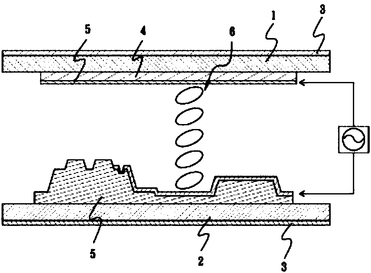
[0005] However, the polarizer 3 is arranged on the outer surface of the upper glass substrate 1 and the lower glass substrate 2, which will cause the light emitted by the backlight to be blocked, and each layer structure in the panel is not 100% light-transmitting material. Therefore, the panel The more layers in the structure, the lower the overall light transmittance, resulting in higher heat generation and power consumption, and lower color brightness
[0006] The current panel design focuses on reducing power loss and increasing light transmittance. Generally, the improvement of light transmittance can be adjusted through the color filter 4, pixel aperture ratio, liquid crystal material and light emitted by the backlight. However, there is no change in the composition and structure of the TFT-LCD panel. Similarly, setting a polarizer to change the brightness and viewing angle has a limited effect on improving the light transmittance.

Method used


Image

  • Polarized structure
  • Polarized structure
  • Polarized structure

Examples


Embodiment Construction

[0056] In order to illustrate the central idea of ​​the present invention expressed in the column of the above-mentioned summary of the invention, it is expressed in specific embodiments. Various objects in the embodiments are drawn in proportions, sizes, deformations or displacements suitable for illustration, rather than drawn in proportion to actual components.

[0057] As used herein, the singular forms "a", "an" and "the" also include plural forms unless the context clearly dictates otherwise. Furthermore, it should be understood that when used in this specification, the terms "comprising" and / or "comprising" specify the presence of stated features, panels, sheets and / or layers, but do not preclude the presence or addition of one or more other features, panels , slices and / or layers.

[0058] When an element is referred to as being "connected" or "connected" to another element, it may be directly provided on, coupled or connected to the other element or there may be inte...


PUM


Abstract

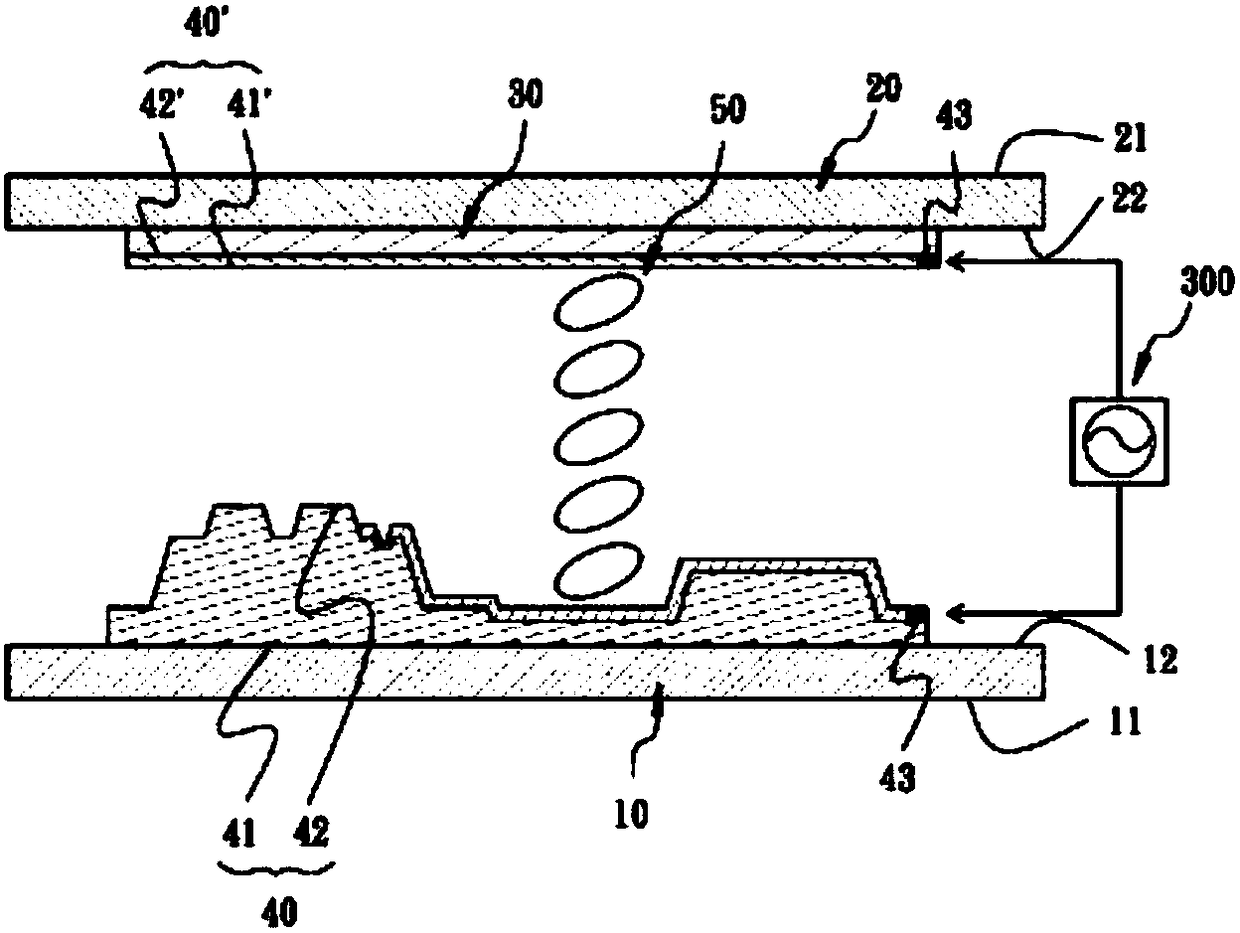
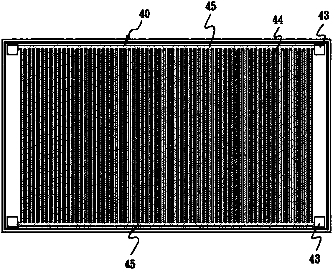
The invention provides a polarized structure comprising a first light transmission substrate which is connected with a backlight source; a second light transmission substrate which is connected with the first light transmission substrate; a color filter which is arranged between the first light transmission substrate and the second light transmission substrate and the color filter is connected tothe second light transmission substrate; two conducting strips which are connected and arranged between the first light transmission substrate and the color filter; the two conducting strips are conductive and are electrically connected with a signal power supply; and a liquid crystal layer connected between the two conductive strips. By eliminating the conventional polarizing plate, the polarizing plate and the filter plate are replaced by two conductive strips, thereby improving the overall light transmittance.

Description

technical field [0001] The invention relates to a liquid crystal display structure, in particular to a polarized light structure. Background technique [0002] Thin-film transistor liquid crystal display (abbreviated as TFT-LCD) is one of most liquid crystal displays. It uses thin-film transistor technology to improve image quality, and it is often used in TVs, flat-panel displays and projectors. [0003] see figure 1 as shown, figure 1 It is the structure of the TFT-LCD panel, which includes: an upper glass substrate 1; a lower glass substrate 2, the outer surface of which is connected to the backlight source; Outer side; a color filter 4, which is located on the inner side of the upper glass substrate 1; two conductive films 5, which are respectively connected to the inner side of the color filter 4 and the lower glass substrate 2; and a liquid crystal 6, which It is arranged between two conductive films 5 . [0004] When a voltage is applied to the two conductive film...

Claims


Application Information

Patent Timeline
Patent Type & Authority Applications(China)
IPC IPC(8): G02F1/1343G02F1/1335
CPCG02F1/133528G02F1/1343G02F1/13439G02F1/133548
Inventor 朱世杰
Owner CHIA SHENG TECH
Learn More