
Valve for controlling exhaust gas or fresh air in a drive unit of a motor vehicle or generator

a technology for motor vehicles and generators, which is applied in the direction of valve details, valve housings, valve arrangements, etc., can solve the problems of high manufacturing cost of valves and high inertia when valves are adjusted, and achieve high stability

Inactive Publication Date: 2021-10-14
VITESCO TECH GERMANY GMBH
View PDF0 Cites 0 Cited by
  • Summary
  • Abstract
  • Description
  • Claims
  • Application Information

AI Technical Summary

Benefits of technology

The invention relates to a valve design that provides stability and reduces the size of the valve body. The valve has an axial support structure that is positioned outside of the mechanically loaded region of the driveshaft, which allows for a smaller diameter of the driveshaft and higher stability. The engine can also be designed with a smaller diameter, cost-effectively manufactured, and has high stability. The cover of the valve can also be manufactured from sheet metal and has high stability. Overall, the invention provides a compact valve that is stable and easy to manufacture.

Problems solved by technology

A large diameter of the driveshaft results in high manufacturing costs of the valve and high inertia when the valve is adjusted.

Method used


Image

  • Valve for controlling exhaust gas or fresh air in a drive unit of a motor vehicle or generator
  • Valve for controlling exhaust gas or fresh air in a drive unit of a motor vehicle or generator

Examples


Embodiment Construction

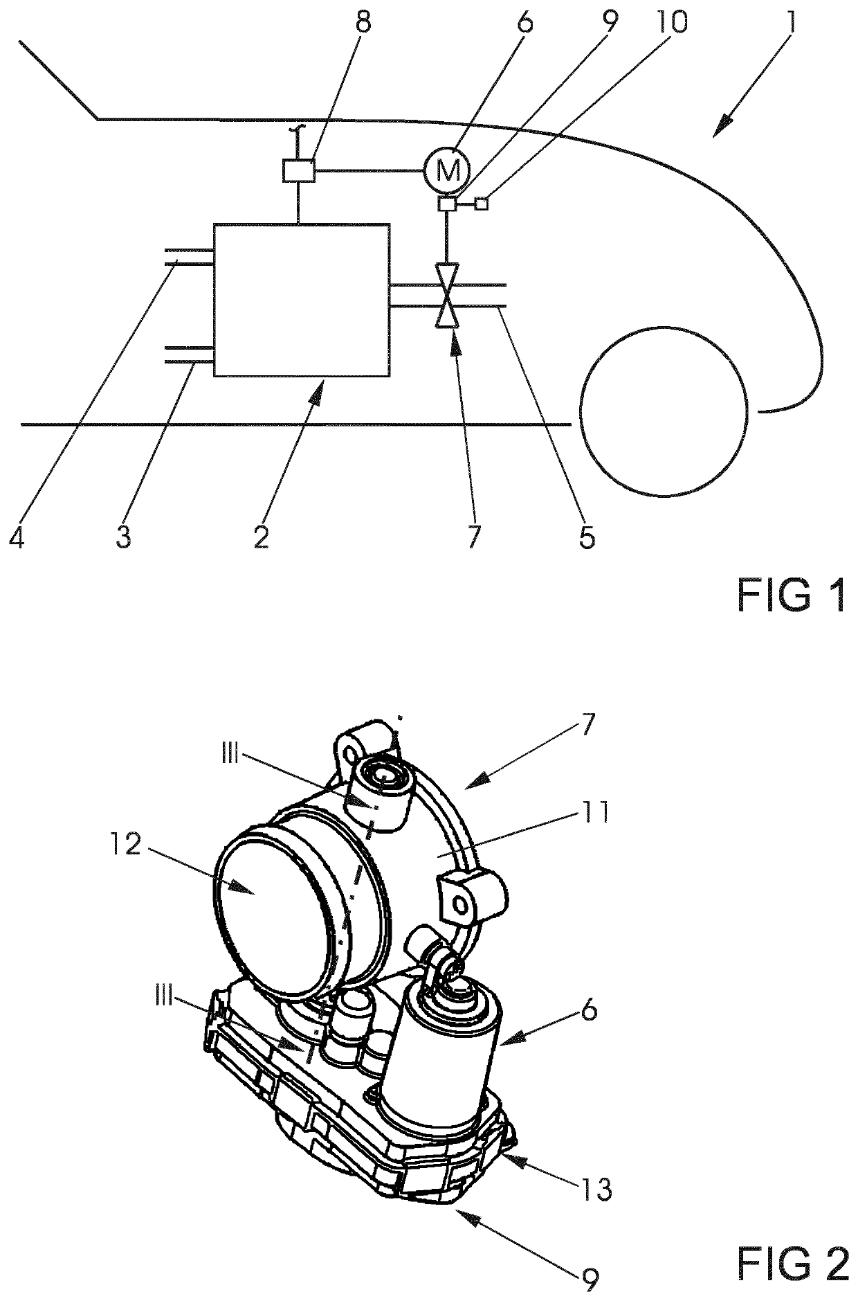
[0022]FIG. 1 schematically shows a subregion of a motor vehicle 1 having a drive unit that has a drive motor 2. The drive motor 2 can mechanically drive the motor vehicle or supply an electric drive (not illustrated) with electric current. The drive unit has two feed ducts 3, 4 for fuel, for example gaseous fuel and fresh air, and an exhaust line 5. The drive motor 2 can be, for example, a fuel cell or an internal combustion engine. Arranged in the exhaust line 5 is a valve 7 that is controllable by an electromotive drive 6.

[0023]In an embodiment that is not illustrated, the valve 7 can also be arranged in the feed duct 3, 4 conducting fresh air or conducting fuel.

[0024]Electric current generated by the drive motor 2 is supplied to a control device 8. The control device 8 is connected to an on-board electrical system (not illustrated) of the motor vehicle.

[0025]The electromotive drive 6 of the valve 7 is supplied with electric current via the control device 8. Arranged between the v...


PUM


Abstract

A valve for controlling exhaust gas or fresh air in a drive unit has an axial support structure arranged at the free end of a driveshaft for a valve body. The axial support structure has a securing ring arranged between a cover pressed into a valve housing and a bearing. The cover seals the valve housing and has an annular bead.

Description

CROSS REFERENCE TO RELATED APPLICATIONS[0001]This is a U.S. national stage of Application No. PCT / EP2019 / 072443 filed Aug. 22, 2019. Priority is claimed on European Application No. EP 18465563.7 filed Aug. 27, 2018 the content of which is incorporated herein by reference.BACKGROUND OF THE INVENTION1. Field of the Invention[0002]The invention relates to a valve for controlling exhaust gas or fresh air in a drive unit of a motor vehicle or generator, having a valve housing that has a duct, a valve body, fastened to a driveshaft for opening or closing a flow cross section of the duct, a drive for pivoting the driveshaft, a bearing for the driveshaft in the valve housing, and an axial support structure for the driveshaft in the valve housing.2. Description of Related Art[0003]Such valves are used in particular in throttle flap connectors or exhaust gas flaps of modern motor vehicles and are known in practice. The valve body is screwed on the driveshaft and is pivoted together therewith....

Claims


Application Information

Patent Timeline
Patent Type & Authority Applications(United States)
IPC IPC(8): F02D9/10F16K27/02
CPCF02D9/106F16K1/224F02D9/1065F16K27/0218F02D9/04F02D9/06F02D9/1035
Inventor ALBERT, EUSEBIO-MARIUSGAVRILA, RAZVAN-GEORGE
Owner VITESCO TECH GERMANY GMBH
Learn More