
Eureka
For R&D, Eureka makes reading and utilizing patents & technical documents easy.
Eureka AIR
Designed for self-driven R&D workflows. Generate viable solutions, solve complex R&D challenges, empower your innovation with AI.

Eureka Materials
Designed for material experts only. Revolutionize your material R&D, from search, analyze, to developing new materials.

TechResearch
Generate reliable direction feasibility study reports for your R&D in just a few steps.

TechSeek
Discover and master advanced knowledge NOW. Basics, ideas, possibilities, all at once.

TechMind
As an expert in R&D Theories, TechMind can generates customized viable solutions instantly.

TechRisk
Analyze your overall solution with one click, know your potential R&D risks in advance.

TechMonitor
Get weekly tech updates, stay abreast of the latest tech innovations and key insights.
Laminated glass set and laminated glass structure
- Summary
- Abstract
- Description
- Claims
- Application Information
AI Technical Summary
Benefits of technology
Problems solved by technology
Method used
Image

Examples
example 1
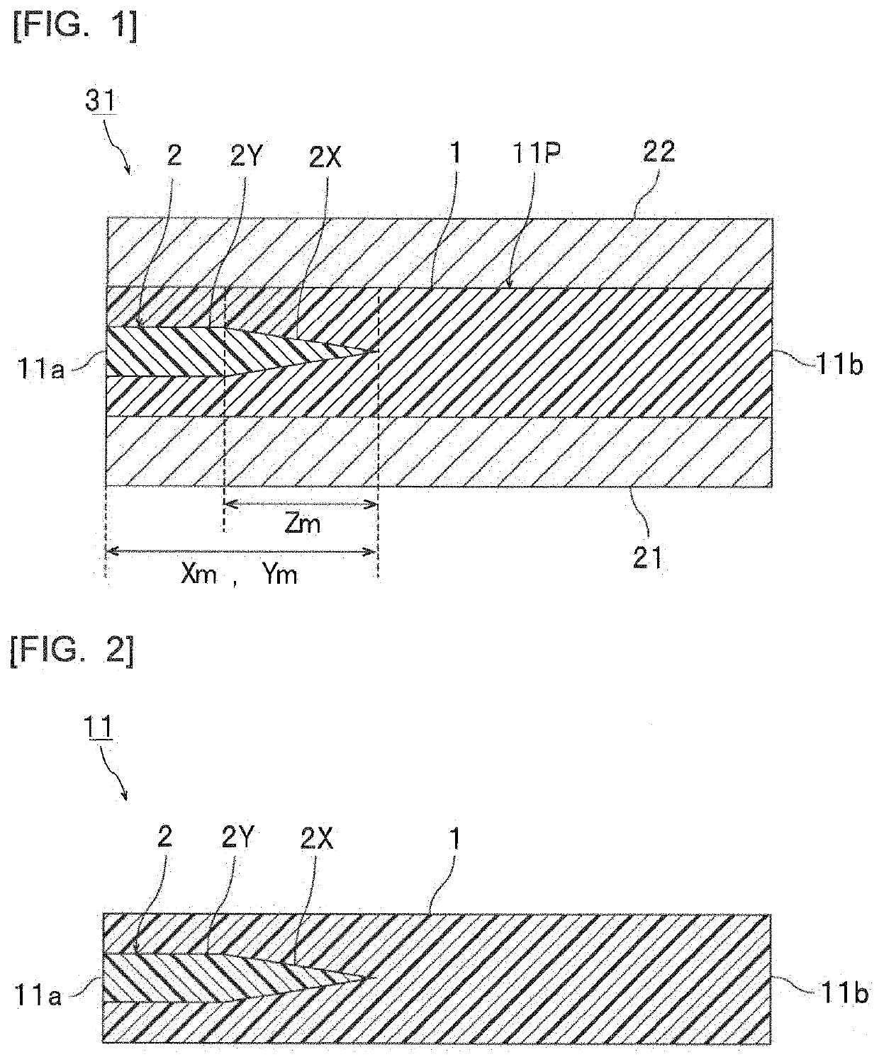
[0343]In Example 1, a plurality of laminated glasses as shown in FIG. 1 were prepared.
[0344]Preparation of Resin Composition for Forming First Resin Layer:
[0345]As shown in the following Table 1, 100 parts by mass of PVB1 and 40 parts by mass of 3GO were mixed, and sufficiently kneaded with a mixing roll, to obtain a resin composition A1 for forming a first resin layer.
Preparation of Resin Composition for Forming Second Resin Layer:
[0346]As shown in the following Table 1, 100 parts by mass of PVB1, 40 parts by mass of 3GO, and calcium carbonate that was mixed so that the concentration in the obtained composition was 6.13% by mass were mixed, and sufficiently kneaded with a mixing roll, to obtain a resin composition B1 for forming a second resin layer.
Preparation of Interlayer Film:
[0347]The resin composition A1 for forming a first resin layer and the resin composition B1 for forming a second resin layer were co-extruded with a co-extruder, and then wound to obtain a roll body of the...
examples 25 and 26
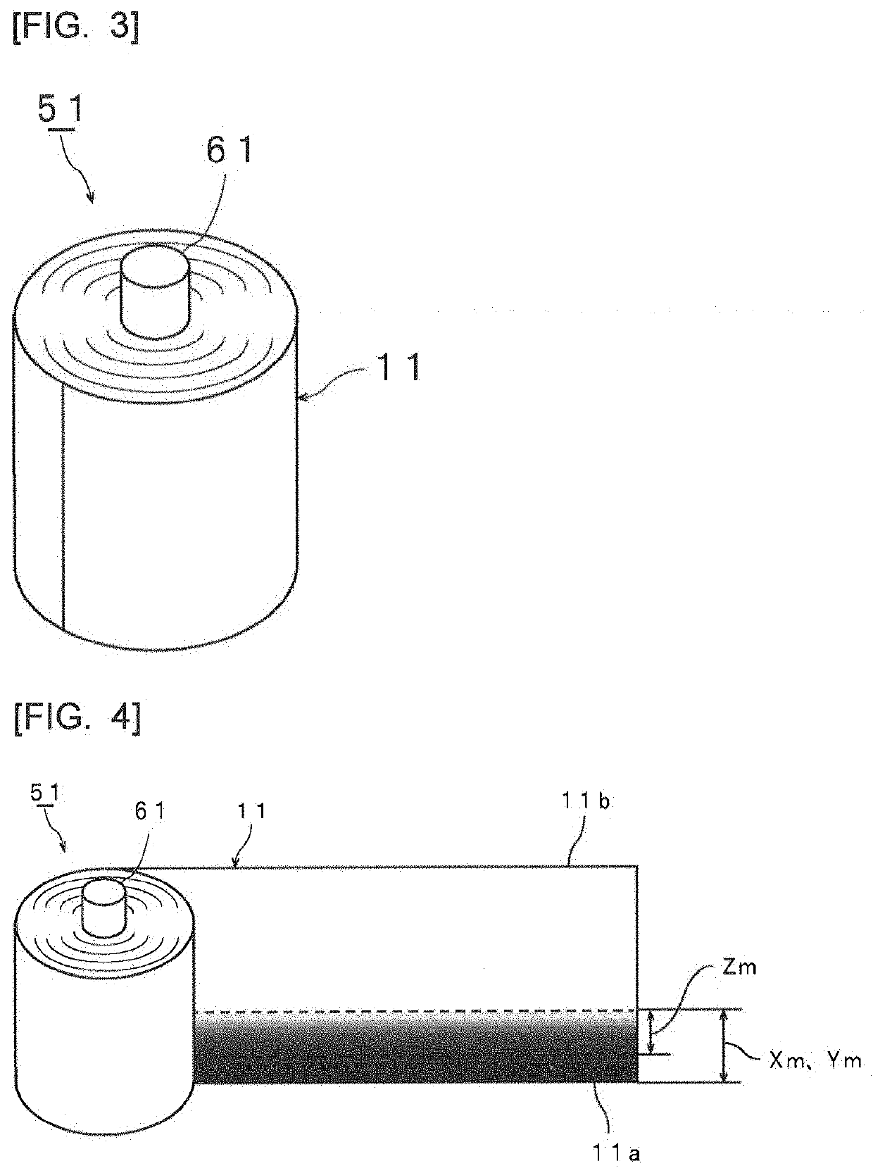
[0353]In Examples 25 and 26, the interlayer film 1 of Example 1 as shown in FIG. 2 (1800 mm wide) was prepared.
[0354]In the same manner as that in Example 1, the interlayer film was prepared, and the interlayer film parts were cut out. Two sheets of clear glass having a thickness of 2.5 mm in conformity with JIS R3202:2011 and having a visible light transmittance of 90.4% were prepared. The clear class had a short-side dimension of 1.5 m and a long-side dimension described in Table 7. Each interlayer film part was sandwiched between two clear glasses such that the short side of the clear glass and one end of the interlayer film part are parallel with each other, and the short side of the clear glass is located at the position described in Table 7 from one end of the interlayer film, and vacuum-pressed by retention at 90° C. for 30 minutes with a vacuum laminator, and thus the stack was temporarily joined. Next, an autoclaving treatment at 130° C. for 20 minutes was performed to obta...
examples 27 and 28
[0356]In Examples 27 and 28, the interlayer film 5 of Example 5 as shown in FIG. 2 (1800 mm wide) was prepared.
[0357]In the same manner as that in Example 1, the interlayer film parts were cut out. Two sheets of clear glass having a thickness of 2.5 mm in conformity with JIS R3202:2011 and having a visible light transmittance of 90.4% were prepared. The clear class had a short-side dimension of 1.5 m and a long-side dimension described in Table 8. Each interlayer film part was sandwiched between two clear glasses such that the short side of the clear glass and one end of the interlayer film part are parallel with each other, and the short side of the clear glass is located at the position described in Table 8 from one end of the interlayer film, and vacuum-pressed by retention at 90° C. for 30 minutes with a vacuum laminator, and thus the stack was temporarily joined. Next, an autoclaving treatment at 130° C. for 20 minutes was performed to obtain 20 laminated glasses.
[0358]In this ...
PUM
| Property | Measurement | Unit |
|---|---|---|
| Length | aaaaa | aaaaa |
| Fraction | aaaaa | aaaaa |
| Fraction | aaaaa | aaaaa |
Abstract
Description
Claims
Application Information
 - R&D Engineer
- R&D Manager
- IP Professional
- Industry Leading Data Capabilities
- Powerful AI technology
- Patent DNA Extraction
Browse by: Latest US Patents, China's latest patents, Technical Efficacy Thesaurus, Application Domain, Technology Topic, Popular Technical Reports.
© 2024 PatSnap. All rights reserved.Legal|Privacy policy|Modern Slavery Act Transparency Statement|Sitemap|About US| Contact US: help@patsnap.com