
Eureka
For R&D, Eureka makes reading and utilizing patents & technical documents easy.
Eureka AIR
Designed for self-driven R&D workflows. Generate viable solutions, solve complex R&D challenges, empower your innovation with AI.

Eureka Materials
Designed for material experts only. Revolutionize your material R&D, from search, analyze, to developing new materials.

TechResearch
Generate reliable direction feasibility study reports for your R&D in just a few steps.

TechSeek
Discover and master advanced knowledge NOW. Basics, ideas, possibilities, all at once.

TechMind
As an expert in R&D Theories, TechMind can generates customized viable solutions instantly.

TechRisk
Analyze your overall solution with one click, know your potential R&D risks in advance.

TechMonitor
Get weekly tech updates, stay abreast of the latest tech innovations and key insights.
Display device
- Summary
- Abstract
- Description
- Claims
- Application Information
AI Technical Summary
Benefits of technology
Problems solved by technology
Method used
Image

Examples
embodiment 1
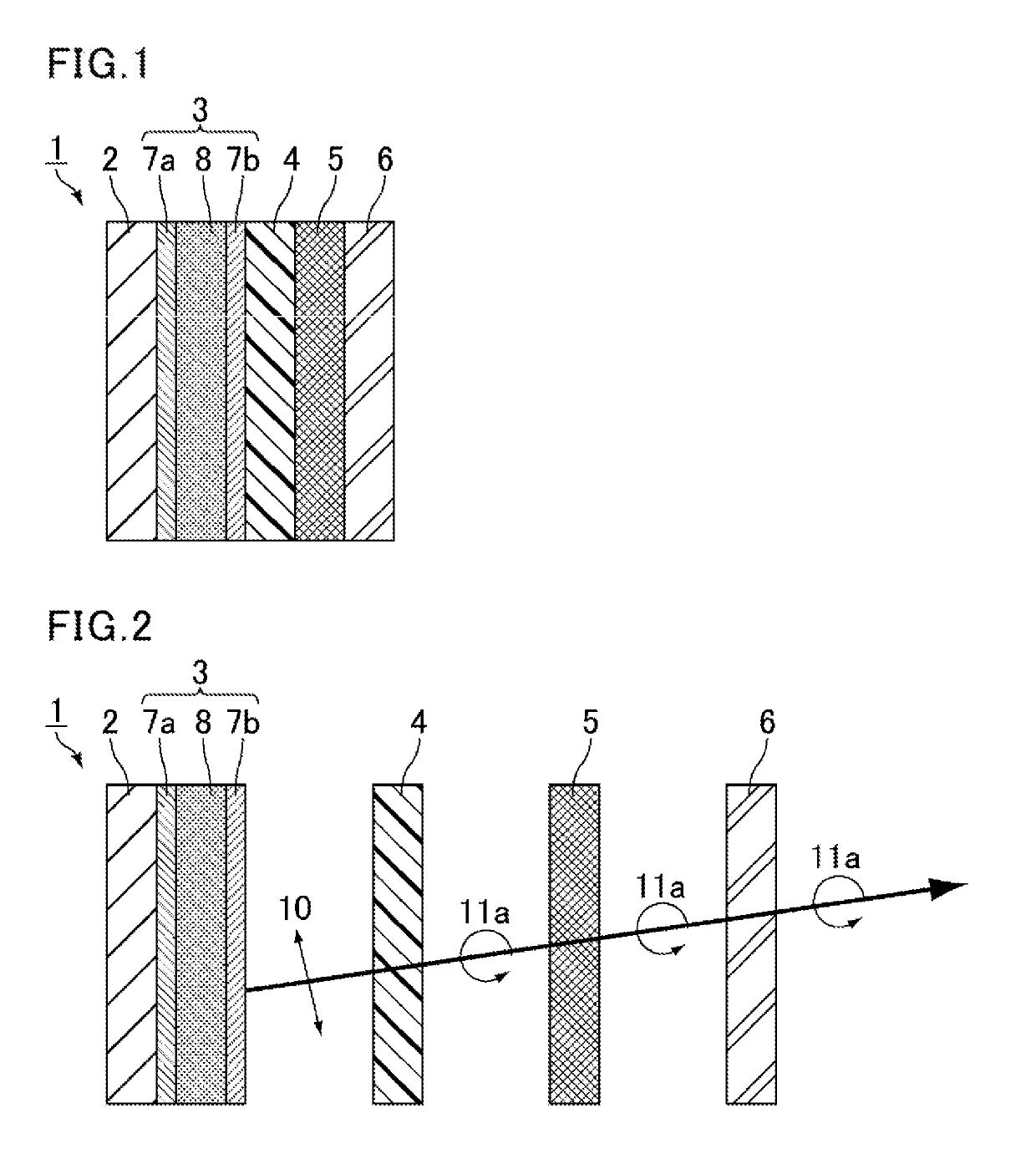
[0019]The following is the description of a display device of Embodiment 1 with reference to FIG. 1. FIG. 1 is a schematic cross-sectional view of a display device of Embodiment 1.
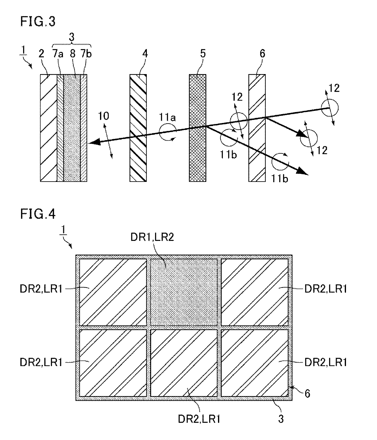
[0020]A display device 1 includes, in the following order: a backlight 2, a liquid crystal display panel 3, a λ / 4 retardation layer 4, a circularly polarized light ray reflection layer 5, and a light scattering layer 6.
[0021]The backlight 2 may be a conventionally known backlight. The type of the backlight 2 is not particularly limited and examples thereof include an edge light backlight and a direct-lit backlight. The light source of the backlight 2 may be of any type such as light emitting diodes (LEDs) and cold cathode fluorescent lamps (CCFLs).
[0022]The liquid crystal display panel 3 can switch between the display mode of emitting display light and the non-display mode of not emitting display light. Examples of display light include linearly polarized light rays, circularly polarized light rays, and el...
adjustment example 1
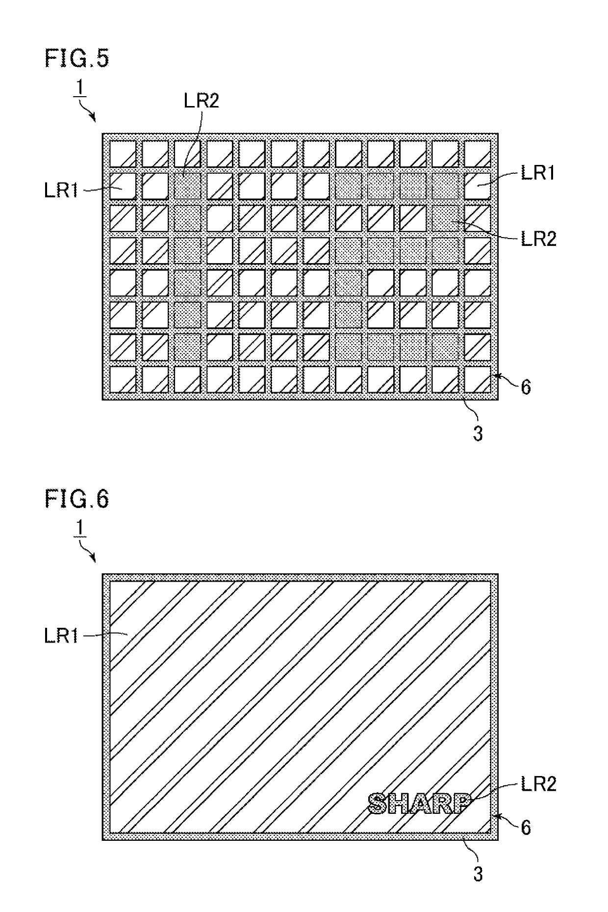
[0049]The circularly polarized light ray reflection layer 5 may reflect the circularly polarized light ray lib with any wavelength falling within the wavelength range of visible light (typically 380 nm to 780 nm). Thereby, the display device 1 appears white in the non-display state. Such a state may be achieved by, in the circularly polarized light ray reflection layer 5, continuously varying the helical pitch of the cholesteric liquid crystal so as to allow the helical pitch to cover the whole wavelength range of visible light.
adjustment example 2
[0050]The circularly polarized light ray reflection layer 5 may reflect the circularly polarized light ray lib with a wavelength in part of the wavelength range of visible light. Thereby, the display device 1 appears in a certain color other than white in the non-display state. For example, when the helical pitch of the cholesteric liquid crystal in the circularly polarized light ray reflection layer 5 is adjusted to 500 nm to 600 nm, the display device 1 appears green in the non-display state.
PUM
| Property | Measurement | Unit |
|---|---|---|
| Wavelength | aaaaa | aaaaa |
| Light | aaaaa | aaaaa |
| Reflection | aaaaa | aaaaa |
Abstract
Description
Claims
Application Information
 - R&D Engineer
- R&D Manager
- IP Professional
- Industry Leading Data Capabilities
- Powerful AI technology
- Patent DNA Extraction
Browse by: Latest US Patents, China's latest patents, Technical Efficacy Thesaurus, Application Domain, Technology Topic, Popular Technical Reports.
© 2024 PatSnap. All rights reserved.Legal|Privacy policy|Modern Slavery Act Transparency Statement|Sitemap|About US| Contact US: help@patsnap.com