Stripping of metal from cathodes

Pending Publication Date: 2021-10-21
MESCO INC +1
View PDF0 Cites 1 Cited by
  • Summary
  • Abstract
  • Description
  • Claims
  • Application Information

AI Technical Summary

Benefits of technology

The present invention is about a way to take metal off a cathode plate while keeping the connections between the metal sheets intact. This method and apparatus make sure that the metal is stripped effectively while still keeping the sheet connection strong. This results in good throughput for the process.

Problems solved by technology

In other plants, the bottom edge of the cathode plates are not waxed or fitted with bottom strips prior to deposition of metal, which results in metal also being deposited along the bottom edge of the cathode plate.
However, if the metal that has deposited on the bottom edge of the cathode plate does not break during the initial stripping operation, it is necessary to flex the sheets upwardly and then downwardly until that metal breaks.
It has been found that such stripping systems are more complex and to achieve high machine throughputs (for example, around 500 cathodes per hour), two stripping stations have been required in the stripping machines.

Method used


Image

  • Stripping of metal from cathodes
  • Stripping of metal from cathodes
  • Stripping of metal from cathodes

Examples


Embodiment Construction

[0066]It will be appreciated that the drawings have been provided for the purpose of illustrating preferred embodiments of the present invention. Therefore, the skilled person will understand that the present invention should not be considered to be limited solely to the features as shown in the drawings.

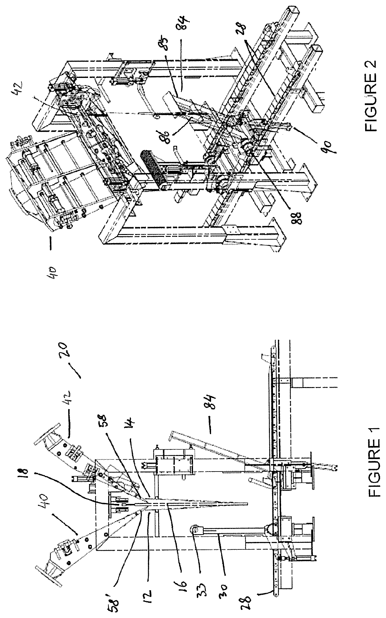
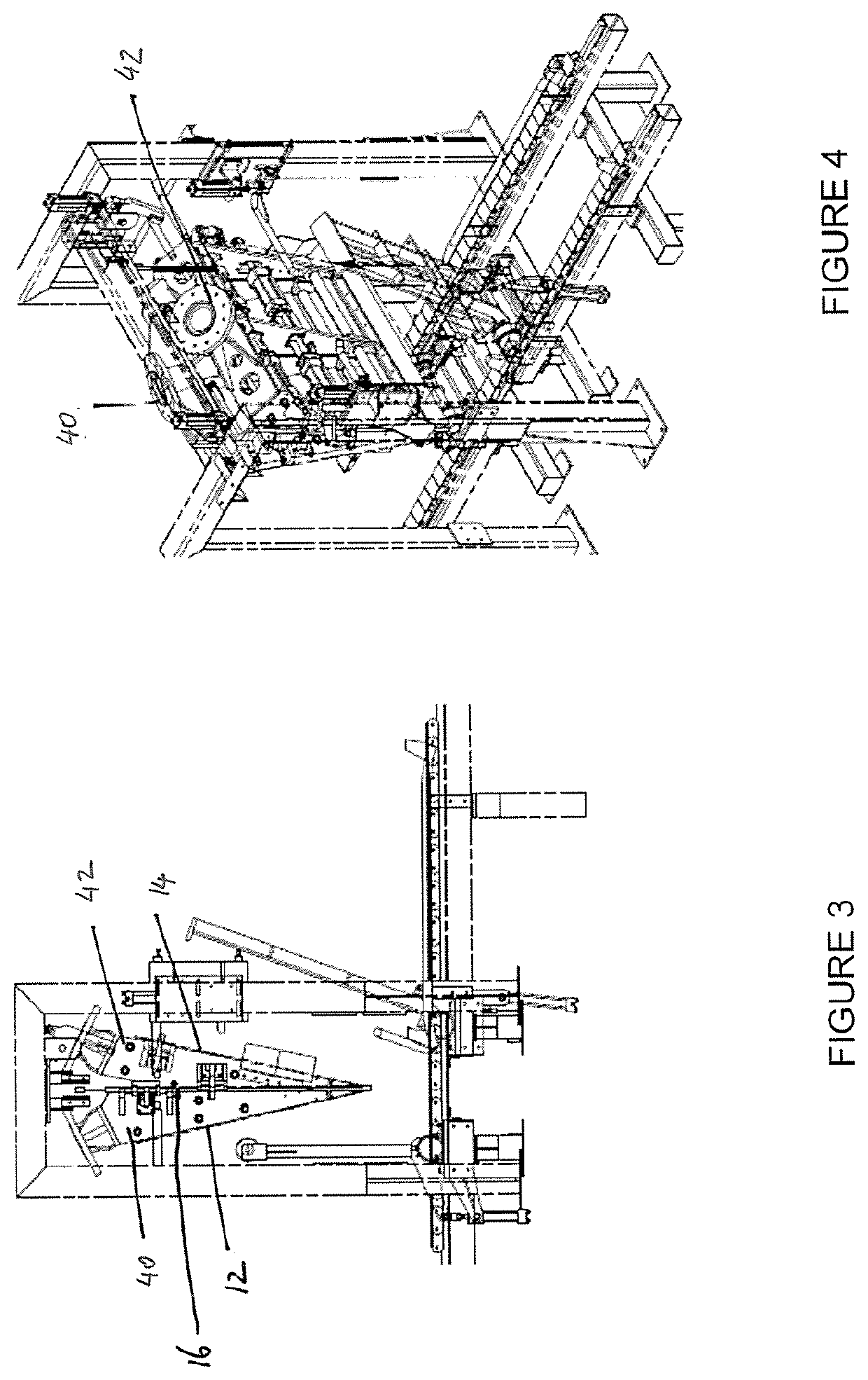
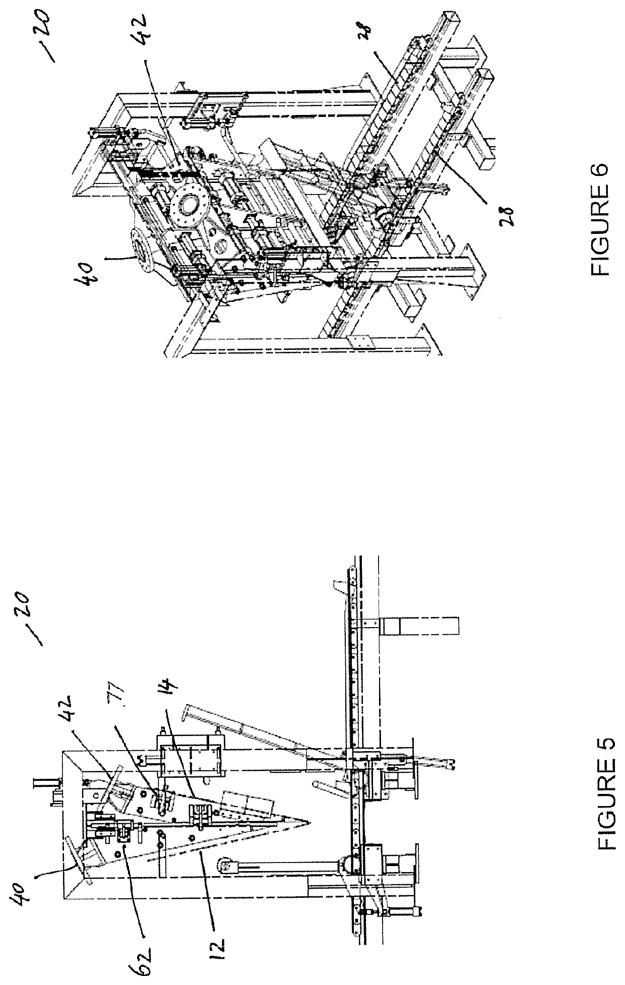
[0067]Turning initially to FIG. 15, which shows an apparatus suitable for use in the method of the present invention, it can be seen that sheets of deposited metal 12, 14 are removed from a cathode plate 16 upon which the sheets of metal been deposited during an electricowinning or an electrodeposition process. The cathode plate 16 typically comprises a stainless steel plate connected to a hanger bar 18. The cathode plate is of conventional construction and need not be described further.

[0068]The deposited metal 12, 14 is removed from the cathode plate in a stripping station 20. Stripping station 20 includes a support frame comprising 4 uprights, 3 of which are shown at 22, 23, 24 a...


PUM

PropertyMeasurementUnit
Angleaaaaaaaaaa
Angleaaaaaaaaaa
Angleaaaaaaaaaa

Abstract

An apparatus for stripping metal (12, 14) deposited on a cathode plate (16), comprises a first robotic arm (46) carrying a first stripping apparatus (40), the first stripping apparatus having a first gripping apparatus (62, 63) to grip the cathode plate such that the first robotic arm operates to lift the cathode plate out of the stripping station following stripping of the metal sheets from the cathode plate. A second robotic arm (48) carrying a second stripping apparatus (42) is located on a second side of the cathode plate, the second stripping apparatus having a second gripping apparatus (76, 77) for gripping one or both of the first sheet of metal (12) and the second sheet of metal (14). The second robotic arm can be operated to move the first sheet of metal and the second sheet of metal to a metal storage region following stripping from the cathode plate (16). The metal is stripped from the cathode plate without breaking the bridge of metal that interconnects the first sheet of metal and the second sheet of metal.

Description

TECHNICAL FIELD[0001]The present invention relates to a method for stripping metal from a cathode plate. The present invention also relates to an apparatus for stripping metal from a cathode plate.BACKGROUND ART[0002]Production of metal using electrochemical processes involves deposition of the metal on a cathode plate. For example, in the electrowinning or electrorefining of copper, copper metal is deposited on to stainless steel cathode plates. When the deposited copper metal has grown to a desired thickness, the cathode plate is removed from the electrolysis cell and the deposited metal is stripped from the cathode plate. Some workers in this field refer to the cathode plate as a cathode blade. These terms are used interchangeably.[0003]Stripping of the deposited metal from the cathode plate is desirably conducted using a largely automated process in order to achieve high throughput in the stripping plant. For example, in U.S. Pat. No. 4,840,710, the entire contents of which are ...

Claims


Application Information

Patent Timeline
IPC IPC(8): C25C7/08B25J9/00
CPCC25C7/08B25J9/0093C25D1/04C25D1/20C25C1/12Y02P10/20
Inventor ERIKSSON, PER OLAKIMLIN, NOEL DOUGLASKIMURA, NAOFUMI
Owner MESCO INC
Why Eureka
Try Eureka