Multi-energy static security ct system and imaging method

Pending Publication Date: 2021-10-21
NANOVISION TECHNOLOGY (BEIJING) CO LTD
View PDF1 Cites 1 Cited by
  • Summary
  • Abstract
  • Description
  • Claims
  • Application Information

AI Technical Summary

Benefits of technology

[0021]According to the static security CT system provided by the present invention, the plurality of single-stage image chain units composed of the multi-focus X-ray sources and the detector assemblies are used to form the N-stage image chain structures. Through exposure of different sequential ray sources in the N-stage image chain structures, images with higher time resolution and more energy levels than a sp

Problems solved by technology

In the spiral CT system, ray sources and detectors need to rotate around a to-be-checked object, and each component needs to bear huge centrifugal force in the rotation process, which puts forward high requirements for the design of key components, and has

Method used


Image

  • Multi-energy static security ct system and imaging method
  • Multi-energy static security ct system and imaging method
  • Multi-energy static security ct system and imaging method

Examples


Embodiment Construction

[0030]Technical contents of the present invention are further described in detail below with reference to the accompanying drawings and specific embodiments.

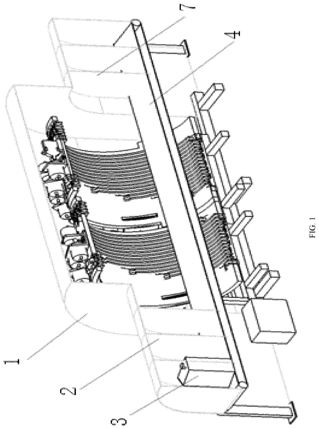
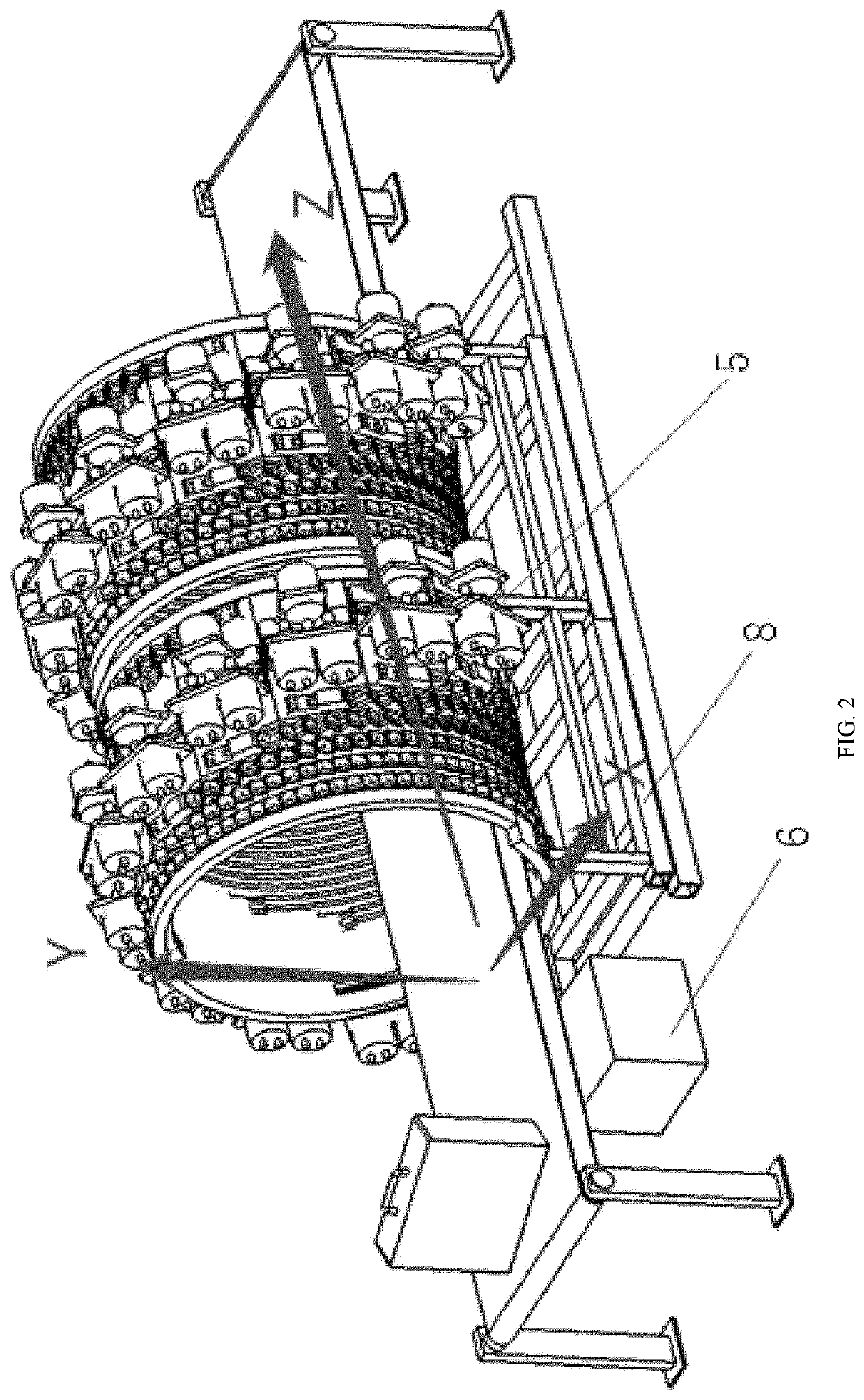
[0031]As shown in FIG. 1 and FIG. 2, the static security CT system provided by the present invention includes a shell 1, a goods inlet shielding curtain 2 and a goods outlet shielding curtain 7 that are sequentially connected. At least one group of N-stage image chain structures 5 is disposed in the shell 1. A baggage conveying belt 4 is disposed on an inner side of bottoms of the N-stage image chain structure 5. The N-stage image chain structures 5 and the baggage conveying belt 4 are fixed to preset positions of the static security CT system through a machine frame 8. Therefore, the baggage conveying belt 4 conveys checked baggage (or luggage, hereinafter) or parcels 3 to the N-stage image chain structures 5. Collection of projection data is completed through the N-stage image chain structures 5. The collected projection data ...


PUM


Abstract

A multi-energy static security CT system comprises at least one N-stage image chain structure (5) and a baggage conveying belt (4) provided at an inner side at the bottom of the N-stage image chain structure (5). The N-stage image chain structure (5) and the baggage conveying belt (4) are fixed at a pre-configured positions by means of a machine frame (8). The N-stage image chain structures (5) are sequentially arranged in a forward direction of a baggage channel, and adjacent N-stage image chain structures (5) are offset relative to each other. By exposing radiation sources in the N-stage image chain structure (5) at different times, the static security CT system generates an image having a higher temporal resolution and more energy spectrum levels than an image generated by a spiral CT system. Also provided is an imaging method implemented by means of the static security CT system.

Description

BACKGROUNDTechnical Field[0001]The present invention relates to a multi-energy static security CT system (hereinafter referred to as a static security CT system), also relates to an imaging method used by the static security CT system, and belongs to the technical field of radiation imaging.Related Art[0002]Existing security CT systems can be divided into two types, one is a spiral CT system based on a slip ring technology, and the other is a static CT system. In the spiral CT system, ray sources and detectors need to rotate around a to-be-checked object, and each component needs to bear huge centrifugal force in the rotation process, which puts forward high requirements for the design of key components, and has high implementation cost and technical difficulty. There is no slip ring in the static CT system, ray sources and detectors do not have to rotate relative to the to-be-checked object, which has the characteristics of high inspection speed, low maintenance cost, high reliabil...

Claims


Application Information

Patent Timeline
IPC IPC(8): G01V5/00
CPCG01V5/005
Inventor LI, BAOLEIHU, YANTAOLI, YUNXIANGCUI, ZHILIGAO, JIANLUO, JIE
Owner NANOVISION TECHNOLOGY (BEIJING) CO LTD
Why Eureka
Try Eureka