Check patentability & draft patents in minutes with Patsnap Eureka AI!

Error correcting decoding device and error correcting decoding method

Active Publication Date: 2021-10-21
MITSUBISHI ELECTRIC CORP
View PDF6 Cites 2 Cited by
  • Summary
  • Abstract
  • Description
  • Claims
  • Application Information

AI Technical Summary

Benefits of technology

The present invention provides an error correction decoding device and method that reduces power consumption during decoding processing.

Problems solved by technology

However, there is a limitation on the number of error bits that can be corrected.
On the other hand, the LDPC code tends to be not as effective for correction in a situation in which an error before correction is relatively small as a correction result obtained in a situation in which an error before correction is large.
The decoding circuit of the error correction circuit requires a high-speed clock for iterative operation processing, which also increases the power consumption.

Method used


Image

  • Error correcting decoding device and error correcting decoding method
  • Error correcting decoding device and error correcting decoding method
  • Error correcting decoding device and error correcting decoding method

Examples


first embodiment

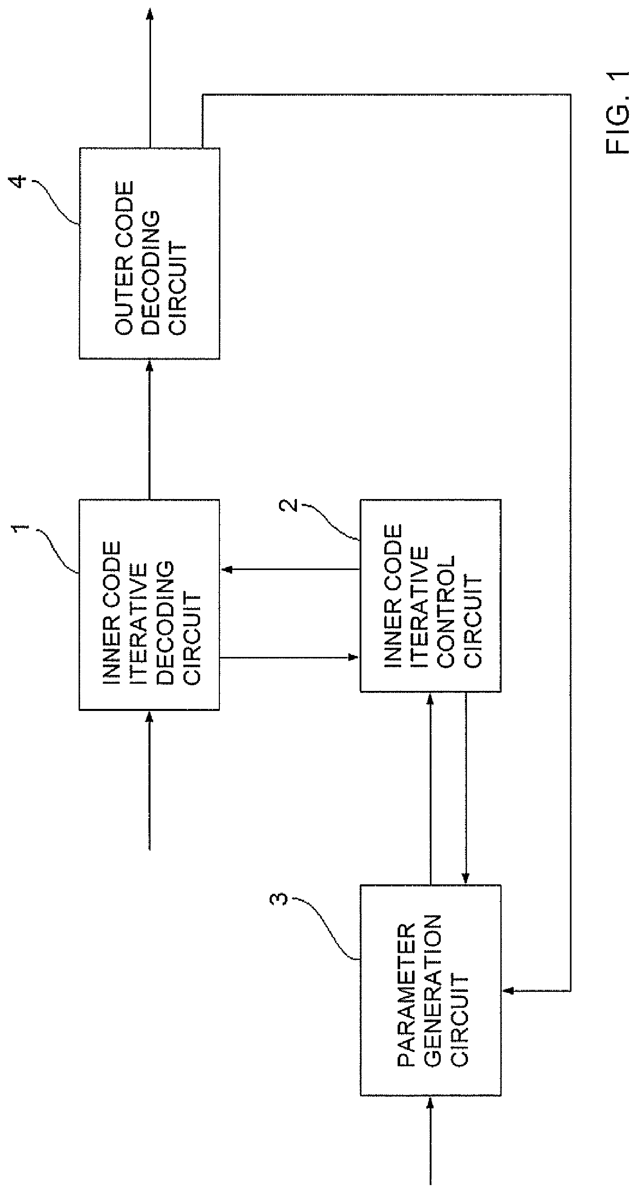
[0038]FIG. 1 is a block diagram for illustrating a configuration example of an error correction decoding device according to a first embodiment of the present invention. In FIG. 1, a configuration of the error correction decoding device using a concatenated code that has an LDPC code as an inner code and a BCH code as an outer code is illustrated as an example. The error correction decoding device illustrated in FIG. 1 includes an inner code iterative decoding circuit 1, an inner code iterative control circuit 2, a parameter generation circuit 3, and an outer code decoding circuit 4.

[0039]The inner code iterative decoding circuit 1 is an iterative decoding circuit configured to perform iterative decoding processing on an LDPC code. The inner code iterative control circuit 2, on the other hand, is a first control circuit configured to control iterative operation of the inner code iterative decoding circuit 1. From the inner code iterative decoding circuit 1, a non-zero-value count S ...

second embodiment

[0081]The preceding description of the first embodiment is focused on a case of suppressing power consumption by controlling the number of times of iteration in iterative decoding processing of an LDPC code sequence. A second embodiment of the present invention, on the other hand, gives description on a case of suppressing power consumption by aborting decoding processing in the middle of the run when an error uncorrectable even in decoding processing with the subsequent block code occurs.

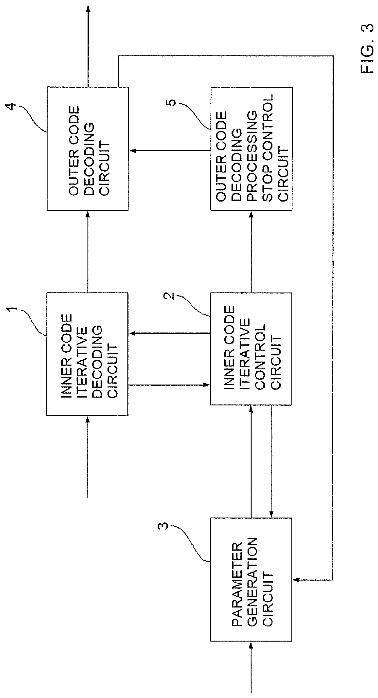
[0082]FIG. 3 is a block diagram for illustrating a configuration example of an error correction decoding device according to the second embodiment of the present invention. The error correction decoding device according to the second embodiment includes the inner code iterative decoding circuit 1, the inner code iterative control circuit 2, the parameter generation circuit 3, the outer code decoding circuit 4, and an outer code decoding processing stop control circuit 5.

[0083]The configuration of F...


PUM


Abstract

Provided is an error correction decoding device including an inner code iterative decoding circuit, a parameter generation circuit, and a first control circuit. The first control circuit is configured to: receive, as parameters, a threshold and a maximum iteration count which are generated by the parameter generation circuit; and compare, when an iteration count does not reach the maximum iteration count, a non-zero-value count sequentially output from the inner code iterative decoding circuit and the threshold set for each iteration count, and stop an iterative operation by the inner code iterative decoding circuit when a result of the comparison satisfies a stopping condition set in advance.

Description

CROSS REFERENCE TO RELATED APPLICATION[0001]This application is a Continuation of PCT International Application No. PCT / JP2019 / 006837, filed on Feb. 22, 2019, which is hereby expressly incorporated by reference into the present application.TECHNICAL FIELD[0002]The present invention relates to an error correction decoding device and an error correction decoding method which are configured to use iterative decoding processing on a low-density parity-check code.BACKGROUND ART[0003]In general, a high-speed transmission device, for example, an optical transmission system, employs an error correction code as an effective method for achieving a high transmission capacity and long-distance transmission. The error correction code is a technology used in, for example, a wired / wireless communication system and a storage device. The error correction code is a technology for adding a redundant bit to digital data to be transmitted on a transmission side, to thereby enable correction of a bit err...

Claims


Application Information

Patent Timeline
IPC IPC(8): H03M13/29H03M13/25H03M13/43
CPCH03M13/2948H03M13/43H03M13/255H03M13/2915H03M13/1111H03M13/1128H03M13/152H03M13/3715H03M13/2906
Inventor YOSHIDAKONISHI, YOSHIAKIISHII, KENJISUGIHARA, TAKASHI
Owner MITSUBISHI ELECTRIC CORP
Features
  • R&D
  • Intellectual Property
  • Life Sciences
  • Materials
  • Tech Scout
  • Unparalleled Data Quality
  • Higher Quality Content
  • 60% Fewer Hallucinations
Learn More