Heating element and method of use

a heating element and heat sink technology, applied in the field of heat sinks and methods of use, can solve the problems of reducing the amount of current that can flow, reducing the conductivity, and a potential failure of the joints in the heating element,

Pending Publication Date: 2021-10-21
TUTCO
View PDF0 Cites 1 Cited by
  • Summary
  • Abstract
  • Description
  • Claims
  • Application Information

AI Technical Summary

Benefits of technology

[0032]In one aspect of the invention, a heating element is provided that comprises first and second terminals and one or more heating element segments extending between the first and second terminals. Each heating element segment has a plurality of cutouts arranged in a repeating pattern, each cutout having an elliptical or obround shape. The first and second terminals and the one or more heating element segments are a continuous single sheet of material, and wherein at least one of the first and second terminals includes an extension part that can be folded with respect to the heating element. In another embodiment, each of the first and second terminals can include an extension part that is folded with respect to the heating element. The folding of the extension parts allows the heating element to stand alone in a given heating application or be used for mechanical attachment of the heating element to a desired structure or location.

Problems solved by technology

One benefit is that joints in a heating element are a potential source of failure because the joint can oxidize over time with the exposure to electricity and oxygen.
Oxidation reduces the conductivity at that point, reducing the amount of current that can flow and creating a cold spot.
Given the many easy to configure and control design factors, the usage could be almost limitless in heating.
However, improvements are still needed with respect to heater elements like that shown in FIGS. 1-4 as their designs can cause manufacturing problems and are basically two dimensional by nature and have more limited applications as a result thereof.

Method used


Image

  • Heating element and method of use
  • Heating element and method of use
  • Heating element and method of use

Examples


Embodiment Construction

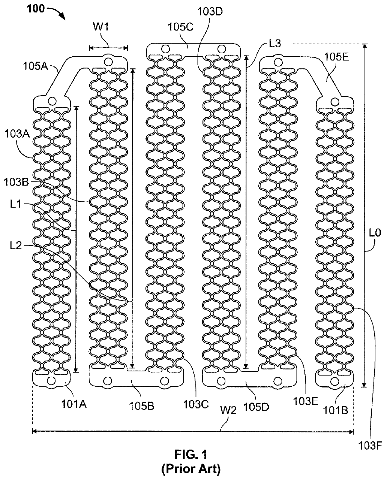
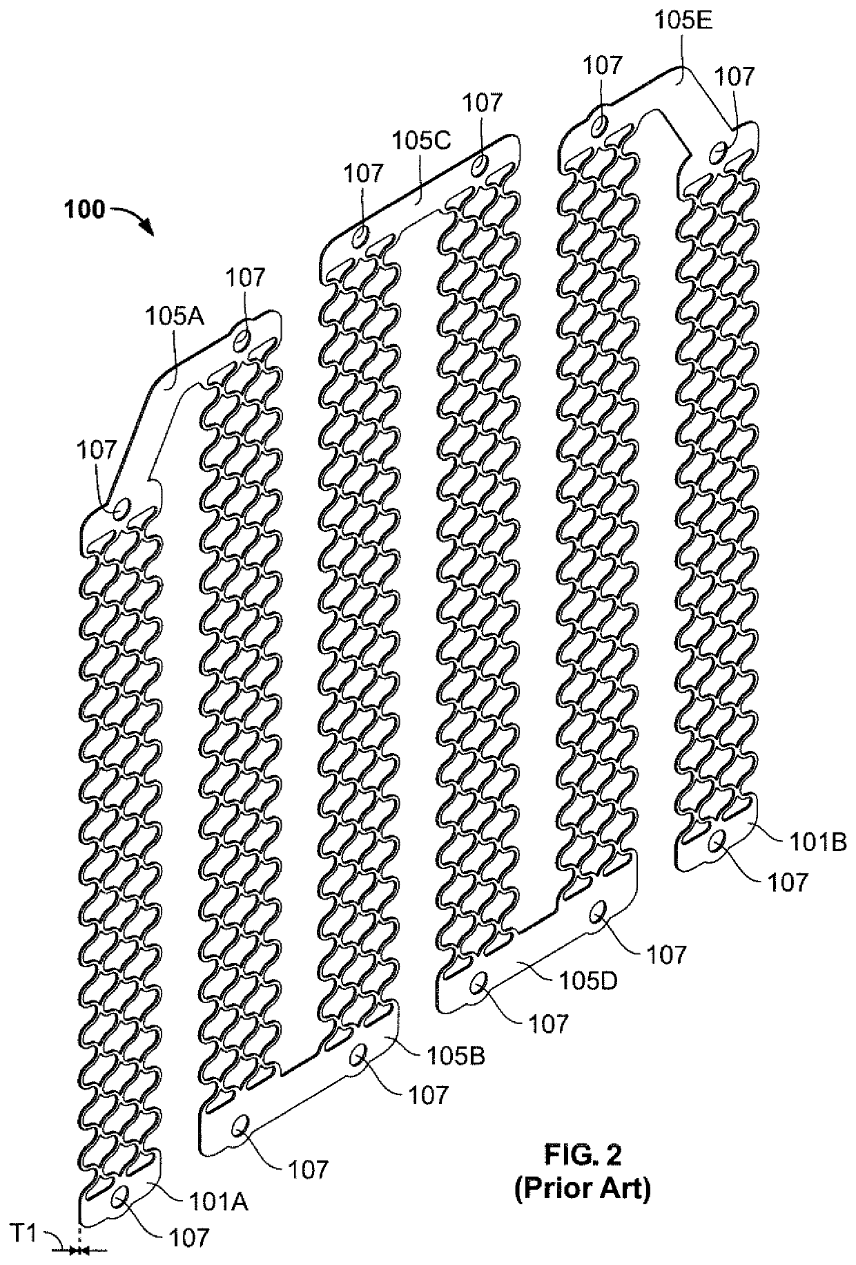
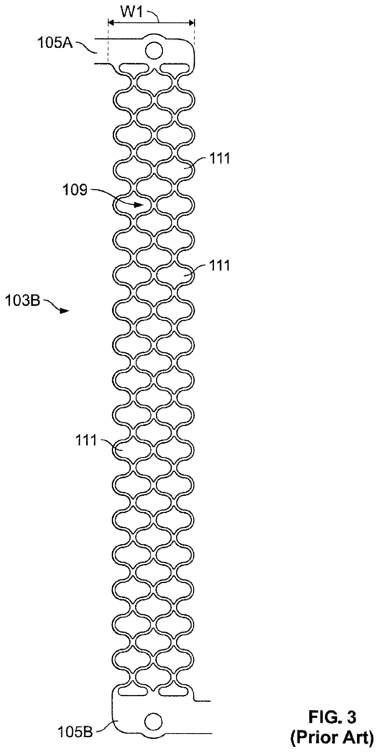
[0079]A number of different heating element designs are provided below that provide improvements over heating element designs such as depicted in FIGS. 1-4 above.

[0080]FIG. 5 shows one embodiment of the inventive heating element, which is designated by the reference numeral 200. The heating element 200 has terminals 201A and 201B, heating element segments 203A-F, and busses 205A-205E.

[0081]The terminals 201A and 201B are custom configured as compared to the terminals 101A and 101B of FIG. 1. That is, each terminal 201A, 201B, includes a fastener 207, that is secured to a backing plate 209. The terminals also include a connector 211, which is designed to connect to wiring for power or another heating element.

[0082]One difference between the heating element 200 in FIG. 5 and that of FIG. 1 is that the lengths of the segments are all the same. With this similarity in length, the busses 205A-205E are the same and do not require any bent portions or elbows as is the case for the heating ...


PUM


Abstract

A heating element includes first and second terminals and one or more heating element segments extending between the first and second terminals. The one or more heating element segments have a circuit trace that includes at least first and second portions, the at least first and second portions configured so that a surface temperature difference exists between the at least first and second portions when a voltage is applied between the at least first and second terminals. The heating element can also be made with a three dimensional shape, including one that is generated by fastening of the heating element to one or more support plates. The heating element can also have a cylindrical shape and be disposed in an insulating medium in a tubular member to provide varied heating capability along the tubular member length.

Description

[0001]This application claims priority under 35 USC 119(e) based on provisional application No. 63 / 010,922, filed on Apr. 16, 2020, which is herein incorporated in its entirety.FIELD OF THE INVENTION[0002]A heating element with a zig-zag pattern is disclosed that includes a unique configuration that can be used in various heating applications.BACKGROUND OF THE INVENTION[0003]In the field of heating elements, expanded type heating elements are well known. U.S. Pat. No. 3,789,417 to Bittner is one example of an expanded type heating element assembly that includes a zig-zag pattern of the heating element material, the pattern creating openings in the heating element material as well.[0004]Other patterned heating elements are disclosed in U.S. Pat. No. 7,763,833 to Hindel et al., U.S. Pat. No. 7,211,772 to Carpino II et al., and Pre-Grant Publication No. 2007 / 0164015 to Carpino II et al., all of which assigned to Goodrich Corporation. For the most part, the patterned heating elements of...

Claims


Application Information

Patent Timeline
Patent Type & Authority Applications(United States)
IPC IPC(8): H05B3/36
CPCH05B3/36H05B2203/011H05B2203/003H05B3/12H05B6/68F24C7/067H05B3/06F24C7/043H01C17/003H01C17/28H05B3/26H05B3/03F24C7/04H05B3/24H05B6/6482H05B2203/004H05B2203/035H05B2203/032H05B2203/007H05B2203/013H05B2203/022
Inventor LOLLAR, JAMES PATRICK
Owner TUTCO
Why Eureka
Try Eureka